© 2011 Thorlabs
51
Operating the Beam Profiler
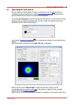
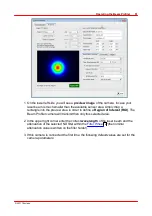
1. On the lower left side you will see a
preview image
of the camera. In case your
laser beam is much smaller than the available sensor area simply drag a
rectangle into the preview area in order to define a
Region of Interest (ROI)
. The
Beam Profiler camera will transmit then only this selected area.
2. In the upper right corner enter the correct
wavelength
of the laser beam and the
attenuation of the selected ND filter within the
(the nominal
attenuation value is written on the filter holder).
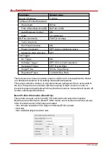
3. If this camera is connected the first time, the following default values are set for the
camera parameters:
9
Summary of Contents for BC106-UV
Page 1: ...2011 Operation Manual Thorlabs Beam Beam Analyzing Software BC106 VIS BC106 UV ...
Page 2: ...Version Date 4 0 11 04 2011 2011Thorlabs 2011Thorlabs ...
Page 76: ... 2011Thorlabs 74 Thorlabs Beam 4 0 Example ...
Page 157: ... 2011Thorlabs 155 Appendix 7 4 4 Drawings 7 4 4 1 BC106 UV ...
Page 158: ... 2011Thorlabs 156 Thorlabs Beam 4 0 7 4 4 2 BC106 VIS ...
Page 159: ... 2011Thorlabs 157 Appendix 7 4 4 3 BC1M2 Mounting Adapter ...
Page 160: ... 2011Thorlabs 158 Thorlabs Beam 4 0 7 4 4 4 Translation Stage VT 80 ...
Page 167: ......

