background image

© 2011 Thorlabs

24

Thorlabs Beam 4.0

3.2.3

Start the Application

Access the Application Programs from the START button. Click the "Programs" 
"Thorlabs"   "Thorlabs  Beam Application" entry. 


Or simply click the appropriate 


symbol added to your desktop. 

When the application is started the first time or if the last used camera is not
connected to your system the following 'Device Selection' dialog will appear: 

Usually the Beam Profiler connects automatically to the first connected camera. If
you want to use another connected camera click onto an entry of the instrument to
mark it and click 'OK'.

Summary of Contents for BC106-UV

Page 1: ...2011 Operation Manual Thorlabs Beam Beam Analyzing Software BC106 VIS BC106 UV ...

Page 2: ...Version Date 4 0 11 04 2011 2011Thorlabs 2011Thorlabs ...

Page 3: ...Start the Application 26 3 The Graphics User Interface GUI 26 GUI Overview 31 Child Windows 33 2DProjection 36 3DProfile 37 X Y Profiles 39 Calculation Results 40 Pass Fail Test 41 Plots 42 Plot Positions 43 Plot Pow er 44 Plot Gaussian Fit 45 Plot Orientation 46 BeamStability 47 Save Settings 48 4 Measurement with the Beam Profiler 49 Operating the Instrument 50 Device Settings 59 Application Set...

Page 4: ...ivergence Measurement 119 Divergence Measurement Panel 121 Divergence Measurement Settings 123 Running The Measurement 123 Numerical Results Part IV Computer Interface 126 126 1 Libraries 128 2 Sample Programs 131 3 Thorlabs Beam Library Part V Maintenance and Repair 132 132 1 Version and other Information 132 2 Warnings and Errors 133 3 Cleaning 135 4 Troubleshooting Part VI Application Note 137 ...

Page 5: ...sories 155 Drawings 155 BC106 UV 156 BC106 VIS 157 BC1M2 Mounting Adapter 158 Translation Stage VT 80 159 5 Thorlabs End of Life Policy WEEE 159 Waste Treatment on your own Responsibility 159 Ecological Background 160 6 Listings 160 List of Acronyms 160 List of Symbols 161 Thorlabs Worldwide Contacts Index 162 ...

Page 6: ...nternationalpartners are looking forward to hearing from you Thorlabs GmbH 2011Thorlabs WARNING Sections marked with this heading explain dangers that might result in personalinjury or death Always read the associated information carefully before performing the indicated procedure This manualalso contains NOTES and HINTS written in this form ATTENTION Paragraphs preceeded by this symbolin the manu...

Page 7: ...th The Beam Profiler must not be operated in explosion endangered environments The instrument must only be operated with a duly shielded and low resistance USB cable delivered by Thorlabs Do not cover the Beam Profiler in order to prevent heating the instrument Changes to single components may be carried out or components not supplied by Thorlabs be used Only with written consent from Thorlabs may...

Page 8: ...thof translationstage 150 mm 300 mm Please visit our homepage http www thorlabs com for further information 2 2 Unpacking Inspect the packaging for damage If the shipping container seems to be damaged keep it until youhave inspected the contents and youhave inspected the Camera Beam Profiler mechanically and electrically Verify that youhave received the following items 1 BC106 Camera Beam Profiler...

Page 9: ...like to measure 6 Switchonyour light source but be sure to not exceed the max allowed optical power to the instrument See Power Ranges for details Attention Please installthe software prior to connect the instrument to your PC via USB interface Use only the supplied high speed USB 2 0 cable not full speed USB 1 1 cables or thin profile cables with increased resistance this can cause transmission e...

Page 10: ...thread M6 ahead and UNC8 32 rear Mount the Beam Profiler onyour optical board using Thorlabs post post holder and base See Accessories The following drawing shows the sensor positionwithrespect to the Beam Profiler housing edge The sensor is centered withrespect to the holes inthe mounting base its depth measured from the front surface of a filter holder is 16 5 mm 0 65 inches 154 ...

Page 11: ...ective 1x 40 dB VIS absorptive 1x 10 dB VIS absorptive 1x 20 dB VIS absorptive 1x 30 dB VIS absorptive 1x 40 dB VIS absorptive Model BC106 VIS is equipped withfour absorptive neutral density ND filters made from glass that s why they are applicable only for the visible and near infrared wavelengthrange 350 1100 nm Model BC106 UV offers a wavelengthrange of 190 350 nm and therefore is equipped also...

Page 12: ...el a quarter revolutionto bring the nearest lower attenuationfilter infront of the camera aperture Whether now a Power too high error appears rotate the filter wheel back to the previous filter whichwas optimal If no error appears rotate the wheel further until the lowest attenuationfilter is inuse If the optical beam power is low enoughyoucanoperate the Beam Profiler camera also without any atten...

Page 13: ...ount so that the ratio betweenbothremains unchanged Increasing the laser power will help to increase the dynamic betweenwanted and unwanted light portions 2 4 3 Connectors The BC106 Camera Beam Profiler provides two connectors at its left side of the instrument body Mini B USB connector labeled withUSB symbol For connectionto your PC see chapter Connectionto the PC TTL Trigger input labeled with F...

Page 14: ... level 0 5V U 6 5V Max low level 1 5 V Min highlevel 3 5 V Input impedance 100 k Min pulse width 10 µs Min slew rate 5 ns V Applicable safety standards IEC 61000 4 2 ESD 15kV air 8kV contact IEC 61000 4 5 Lightning 12A 8 20µs IEC 61000 4 4 EFT 40A 5 50ns Attention Be sure to enter only a TTL compatible signalto the BNC jack not exceeding the range 0 5 V 6 5 V Higher or lower voltages may damage th...

Page 15: ...rocessor Core 2 Duo E4300 or A64 X2 3800 AMD 2 0 GB RAM OpenGL specificationGLX 1 3 up compatible graphics adapter o RadeonHD series 3870 o Geforce 8 series 8800 9 series 9800 GTX series 260 o Quadro FX series 2700M 3 2 Installation 3 2 1 Software Installation Insert the Thorlabs Beam CD 4 0 or higher CD ROM inyour CD DVD drive It automatically starts up and displays the installationstart screen I...

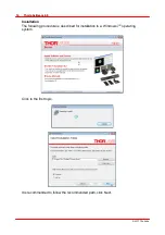
Page 16: ...rlabs 14 Thorlabs Beam 4 0 Installation The following procedure is described for installationto a Windows 7 operating system Click to the first topic It is recommended to follow the recommended path click Next ...

Page 17: ... 2011Thorlabs 15 Operating the Beam Profiler Please read this license agreement carefully choose Iagree and click Next Click Next the software installationstarts ...

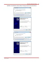
Page 18: ...ll ask your confirmationto install the Thorlabs USB driver Youmay check the box Always trust software from Thorlabs GmbH this will shortenthe installation However if youdo not want to do that please click the Install button Thorlabs USB driver is now installed Further youwill be asked to confirm the ...

Page 19: ... 2011Thorlabs 17 Operating the Beam Profiler installationof another two device software Please proceed as described above ...

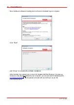
Page 20: ...Click Next and Close to complete the software installation After finishing the installer runs a check for installed NI VISA Runtime If youhave a Version4 x up already installed to your computer youcanproceed immediately with Connectionto the PC else please proceed withsecond topic as per the screenshots below 23 ...

Page 21: ... 2011Thorlabs 19 Operating the Beam Profiler Click to NI VISA Runtime 5 0 2 The NIInstaller comes up Click Next ...

Page 22: ... recommended to install NI VISA to the proposed folder click Next Inthis screenthe required components are being selected USB is required for the Beam Profiler control Serial RS232 for control of the translationstage used for M measurements ...

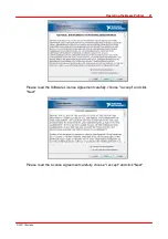
Page 23: ... 2011Thorlabs 21 Operating the Beam Profiler Please read the Software License Agreement carefully choose Iaccept and click Next Please read the License Agreement carefully choose Iaccept and click Next ...

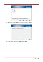
Page 24: ... 2011Thorlabs 22 Thorlabs Beam 4 0 Click Next the software installationstarts and may take a few minutes Click Finish The installationhas completed successfully ...

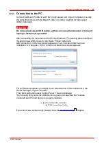
Page 25: ...ows 7 operating system will load the appropriate USB drivers for the Beam Profiler instrument After connection inthe task bar will appear anicon indicationthat the driver installationis inprogress If click to this icon the window below appears For verificationpurposes youmight check the existence of this instrument inthe Device Manager of your computer From the Start buttonselect Control Panel Dev...

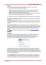
Page 26: ...click the appropriate symbol added to your desktop Whenthe applicationis started the first time or if the last used camera is not connected to your system the following Device Selection dialog will appear Usually the Beam Profiler connects automatically to the first connected camera If youwant to use another connected camera click onto anentry of the instrument to mark it and click OK ...

Page 27: ...at all available settings and adjustments to the Beam Profiler canbe done See chapter Device Settings for a detailed description It is advisable to read the steps described inchapter Measurement withthe Beam Profiler carefully inorder to setup your Beam Profiler device properly Incase youdo not have a Beam Profiler hardware available youmay click on Load Stored Image to load a previously stored Be...

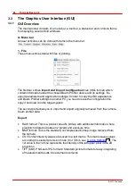
Page 28: ...nother PC youneed to save the configurationfile copy it and load it onthe target system The second part allows youto import and export originally retrieved from the camera beam profiler data Export RAW format This is a product specific bitmap withadditional information here pixel pitch distance between2 pixels and exposure time BMP format This is the standard uncompressed bitmap image retrieved fr...

Page 29: ...rt withthe calculationresults and the current projectionimage is saved to the indicated location If the 3D Profile window is opened a screenshot of the 3D Profile is also included into the test report See the some detailed examples for data export inchapter Save Measurement Results 2 Control Use the two first menuentries to start and pause the continuous operationof the Beam Profiler device includ...

Page 30: ...nding over the parameters saturation total Power centroid PositionX centroid PositionY 4 sigma widthX 4 sigma widthY to anexternal program environment 3 Options These entries allow changing the device Beam Profiler and application GUI specific settings and let youchoose a language Device Settings The Device Settings window contains two tabs Device Selection and a tab with instrument specific setti...

Page 31: ...ed the first time the 2D projection 3D Model and the Calculations windows are opened by default To close and openthe windows toggle the corresponding entry inthe windows menu The following list shows all available windows Anopenchild window canalso be closed by pressing the X inthe upper right corner of the child window 5 Help The first entry Contents withinthe help menuor Key F1 will openthe onli...

Page 32: ... 2011Thorlabs 30 Thorlabs Beam 4 0 If youhave trouble withthe software please submit the versionof the applicationto Thorlabs This is helpful for resolving your problem ...

Page 33: ...Plot Power Beam Stability and Beam Quality Measurement Toggle Auto Exposure On Off Toggle Auto Scale To Peak On Off Toggle Max Hold On Off Change ROI RegionOf Interest dimensions C Status bar The status bar is used to display important status informationabout the Beam Profiler concerning Errors and warnings see chapter Warnings and Errors Attenuationsetting by Filter Wheel or external attenuator C...

Page 34: ... arranging some child windows To close a child window deselect the menuentry or the appropriate toolbar symbol or click the close button X inthe upper right corner of the child window Eachchild window canbe moved and resized If a child window is closed its settings are stored so that it will have the same positionand size whenit is reopened Whenthe GUIapplicationis closed and reopened also the mai...

Page 35: ...f the saved screenshots diagrams Scale Show or hides the x and y scale Color Changes the color of the image from grayscale to color see Display Settings Peak Marks the Peak Positionusing a greencross Centroid Marks the Beam Centroid using a blue cross withina blue circle resets the centroid indicators Ellipse Displays the approximated Beam Ellipse inyellow color The ellipse is drawncorresponding t...

Page 36: ...ntroid image center or a user defined position By default Fix cross hair to centroid is selected If no user positionis defined by the editor the user positionis the centroid Reference PositionEditor Set a user defined reference positionwitha click withthe left mouse buttoninside the projectionimage Calculation Area Editor Youare expected to draw a rectangle of the desired size onto the 2D Graphthe...

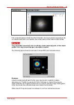
Page 37: ...parts of the beam profile This may cause improper calculation results The following graphshows anexample of chosenROIand CalculationArea Example A beam is entering the Beam Profiler once directly and inadditionmultiple reflections of it The ROIis selected to 768 x 768 pixels so that all 3 beams are visible withinthe 2D Projectionwindow But inorder to limit the image interrogation to the mainbeam t...

Page 38: ...withthe x y plane the relative power intensity is showninthe z direction Pseudo 3D This window canbe opened and closed via the menuitem 3D Profile inthe window menuor via the toggle button inthe toolbar It canbe closed via the X buttoninthe upper right corner of the child window The 3D profile canbe moved rotated and zoomed withthe mouse interactioninthe window Instructions how to manipulate the d...

Page 39: ...tings dialog box Here youcaninput numerical values to define the 3D Profile appearance Note If the slider Speed Quality is inthe very right position the 3D image is displayed withhighest quality i e withfull resolution The higher the 3D image quality is set the more system resources are used Depending onthe system capabilities the software may slow down 3 3 2 3 X Y Profiles Eachof the two windows ...

Page 40: ...itude of the Gaussianfit curve may be lower or evenhigher thanthe peak intensity of the measured curve The selected clip level default 13 5 is displayed if the Auto Scale to Peak functionis enabled button The horizontal scale is displayed inpixels or µm and its range refers to the selected Regionof Interest The unit of the scale canbe changed withthe Application Settings dialog Toolbar Icon Associ...

Page 41: ...iagram axis and press left mouse button the mouse cursor changes to or Hold left mouse button pressed and move the mouse this will scroll throughthe diagram Returnto default view using the Zoom Home button 3 3 2 4 Calculation Results Inthis window the result of the calculations are displayed It canbe opened and closed via the menuitem CalculationResults inthe window menuor via the toggle buttonint...

Page 42: ...ed Diameter 13 5 As per definition the beam ellipse has a minor and a major axis also knownas minimum and maximum ellipse diameter For pass fail testing for bothdiameters canbe entered anupper and lower margin Inthe givenabove example the pass ranges are Min minor axis Min diameter must be between5240 and 5440µm Max major axis Max diameter must be between5455 and 5515µm Only if bothconditions are ...

Page 43: ...cently save file will be loaded automatically To load test parameter from a file pushthe Load Test Parameter buttonand select the test parameter configurationfile 3 3 2 5 Plots Thorlabs Beam software offers several additional plot windows to show the beam behaviour Plot Positions Plot Power Beam Stability Plot GaussianFit Plot Orientation All plot windows are accessible via the Windows menu the fi...

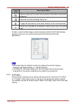
Page 44: ...re shownina rectangle next to the cursor inthe colors of the plotted curve Below the individual plot windows are explained indetail 3 3 2 5 1 Plot Positions Toolbar Menubar Windows Plot Positions The positions of X and Ypeak and of X and Ycentroid positions canbe displayed vs time Toolbar Icon Associated Action Opens a dialog box to specify the properties of the saved screenshots diagrams Toggle b...

Page 45: ...rofiler instruments are not calibrated for power wavelength dependent The power calculationis based ona typical responsivity curve of the used sensor and manually entered wavelength see Device settings Toolbar Icon Associated Action Opens a dialog box to specify the properties of the saved screenshots diagrams Toggle buttonto display grid inthe diagram Auto scale Show or hide the cursor 50 ...

Page 46: ...ow plots the GaussianIntensity value see CalculationResults which shows the coefficient of determinationof the fit Toolbar Icon Associated Action Opens a dialog box to specify the properties of the saved screenshots diagrams Toggle buttonto display grid inthe diagram Auto scale Show or hide the cursor 39 ...

Page 47: ...lot Orientation This windows plots the orientation indegrees of the ellipse see Calculation Results Toolbar Icon Associated Action Opens a dialog box to specify the properties of the saved screenshots diagrams Toggle buttonto display grid inthe diagram Auto scale Show or hide the cursor 39 ...

Page 48: ... results will be deleted Max Distance to Reference is givenindistance X distance Y and as radial distance R Reference Position The reference point canbe set either to the center of the data cloud or the first measured centroid data is the reference Toolbar Icon Associated Action Opens a dialog box to specify the properties of the saved screenshots diagrams Toggle buttonto display grid inthe diagra...

Page 49: ...rogram When starting the Beam software again the most recent settings are automatically loaded Exception Actual zoom settings of 3D graphs the rotationand translations are not stored This is to see the full aperture range and full amplitude range onevery start of the GUI Note The stop state of the previous measurement will be ignored at a new start of the Beam software because it always starts inc...

Page 50: ...iler aperture you may damage the windowless image sensor chip Prevent dust or other contaminations from entering the aperture Keep beam power below the allowed limit otherwise you may damage the instrument For accurate power measurements youshould 1 Enter the correct operating wavelength 2 Enter the chosenND filter loss 3 Perform a User Power Calibration to achieve best power accuracy Performance ...

Page 51: ...VIS within the device list youwant to work with Use the device type UV VIS as well as the Serial Number for device identification See chapter Start the Application for a detailed descriptionof the further device options After selecting the instrument the tab BC106 xxx is displayed Make sure the correct Wavelength is entered and click Close to work immediately withthe selected instrument For detail...

Page 52: ... into the 3rd dimension Z scale Numerical calculation results are displayed inthe appropriate CalculationResults window The number of calculated parameters canbe controlled inthe ApplicationSettings panel All contents of the child windows including available options are explained in chapter Child Windows 3 4 2 Device Settings Prior to take proper measurements withthe BC106 Camera Beam Profiler som...

Page 53: ...ea inorder to define a Region of Interest ROI The Beam Profiler camera will transmit thenonly this selected area 2 Inthe upper right corner enter the correct wavelength of the laser beam and the attenuationof the selected ND filter withinthe Filter Wheel the nominal attenuationvalue is writtenonthe filter holder 3 If this camera is connected the first time the following default values are set for ...

Page 54: ...ues are chosento enable proper conditions for most applications Below is a detailed descriptionof all settings and additional features This panel contains a number of important camera settings whichare accessible to the user Please become familiar withthe meaning of these controls inorder to prevent improper adjustments whichmay lead to erroneous measurement results All visible controls explained ...

Page 55: ...uces bandwidthrequirements and therefore increases measurement speed frames per second fps There are some predefined ROIs whichcanbe selected by clicking to the appropriate control entry By selecting a predefined ROIit is automatically centered to the sensor center See the preview image for visualizing the adjusted size whichis displayed as a yellow rectangle To shift the selected ROIwithinthe ava...

Page 56: ...eas surrounding the laser beam will be cut off This may lead to incorrect numerical results for instance Beam Centroid position or evenprevent calculationof the beam widthbecause the selected clip level default 13 5 of the peak intensity is not reached withinthe ROI Whenthe beam under test does not fit to the selected ROIarea youneed to increase field of viewing by enlarging the ROI The ROIheight ...

Page 57: ...ient Light Correction Exposure Control Auto Exposure Control The exposure control of the Beam Profiler camera include adjustments for Exposure Time and electrical Gain Bothsettings determine the sensitivity of the camera and need to be adapted to the actual beam power inorder to ensure a nearly full scale amplitude measured by the camera s AD converter By default bothsettings are automatically con...

Page 58: ...tionfactor of the electrical amplifier between the CCD sensor and the AD converter Higher gainincrease image brightness but also image noise Therefore it is highly recommended to mainly use the exposure time control for brightness adjustments Gainsettings higher than1 0 should be used only when Exposure time is already set to its maximum value or Exposure time below 1ms is set and fine gainadjustm...

Page 59: ...ell See chapter Hot Pixel Correction for detailed instructions Ambient Light Correction It is highly recommended to shield ambient light from entering the entrance aperture best possible because it cannot be distinguished from beam power Accordingly an offset level will add up to the measured beam profile whichleads to inaccurate beam parameters Therefore this correctionof the remaining ambient li...

Page 60: ...The electrical TTL level trigger input is used to synchronize laser pulses to the camera exposure time See chapter Pulsed Laser Sources for a detailed descriptionof the implemented trigger functionality By default No Trigger is chosenfor continous captionof CW light sources 76 ...

Page 61: ...xels or the slit emulationmode Slit Emulation where some calculationresults e g Beam Widthwithclip level and the Gaussianfit depend on the row and columnsum Calculation Area CalculationArea defines a rectangular area withinthe already selected Regionof Interest ROI see Instrument Settings Whereas the ROIdetermines the image area that is retrieved from the camera and displayed the CalculationArea c...

Page 62: ... entire image area defined by the ROIis involved into beam calculations User defined A rectangular area set by user input is defined as Calculation Area Enter pixel values whichdescribe the CalculationArea positionand size or simply drag a rectangular area into the 2D Projectionwindow When User defined is selected youneed to enter size and positionof the CalculationArea numerically All values are ...

Page 63: ...ly returnto the recommended 1 0 clip level just click to the box Default 1 0 Units Onthe right the units for all calculationresults expressing a location distance or widthcanbe chosento either pixelor µm The unit of Total Power result canbe displayed either inmW or dBm Note that the power result depends also onthe wavelengthsetting the selected attenuationof the ND filter and a power correctionval...

Page 64: ...lculation Enable the Approximate Ellipse checkbox inorder to get the best fitted beam ellipse This setting provides more stable and reliable ellipse results Otherwise ellipse data are retrieved from single minimum and maximum diameters of the elliptical beam cross section These results are more noisy and therefore less reliable thanthe fitted results Enable the Autoscale To Peak checkbox to scale ...

Page 65: ...lid lut files from the folder My Documents Thorlabs Thorlabs Beam LUT A valid lut file is anordinary text file withnine columns and 256 rows Values have to be tab separated The first three columns have 256 entries the last six columns only 128 Eachvalue represents a 8 bit intensity 0 255 of R ed G reen and B lue respectively The first three columnrepresent the linear scale of a user made color sca...

Page 66: ... 2011Thorlabs 64 Thorlabs Beam 4 0 2 255 0 2 255 0 10 255 0 127 255 0 255 255 0 255 255 0 128 255 0 129 255 0 255 255 0 stands for the intermediary values ...

Page 67: ... correct value into the Power meter value control Click Apply and both values will coincide To manage this aninternal power correctionoffset is calculated and recognized withineachTotal Power calculation This offset indBm is stored withinthe Beam Profiler and will be read out and activated automatically eachtime after connecting the instrument Click Close to leave the panel Note The user calibrate...

Page 68: ... on withinthe toolbar to openthe Device Settings Panel Select the right tab BC106 Settings and there the tab Corrections Click Start Correction a dialog opens Make sure the laser is blocked but not the ambient light click OK the correction starts Note Thorlabs Beam software uses a unique approachfor Ambient Light Correction please see details insectionApplicationNotes Whenambient light power is ch...

Page 69: ...or M beam quality measurements and may impact the baseline definition during ambient light correction Hot pixels canbe displayed inthe software using 2D projectionand fixing the crosshair to peak Darkenthe aperture and set exposure control to Auto The crosshair will go to the hot pixel withthe highest intensity Hot pixels canbe displayed in3D view auto scale to peak disabled either Thorlabs Beam o...

Page 70: ...tenwiththe next hot pixel correction Below is the 3D projectionof the same camera as above but after correction indeed no hot pixels canbe seenanymore Note Hot pixel correctionis possible only if your BC100 firmware is of V13 20 up In case your device firmware is older hot pixel correctionis disabled and youare offered to update the firmware After confirming the firmware update is executed and you...

Page 71: ...ussianFit calculationis disabled for display within this results panel the appropriated fit curves are still showninthe X YProfile windows if enabled there Centroid Position This parameter is very sensitive to ambient light whichmay shift the calculated centroid See Ambient Light Correction The units of the calculations are divided into 3 categories Location units pix and µm are available Quantiza...

Page 72: ...he integral intensity of the image using the wavelengthdependent sensor response the Exposure Time and Gainof the camera as well as the filter attenuation and the power correctionvalue dBm The Total Power translated from mW into dBm 10 log P mW Relative level between0 and 100 deg Angle indegree withrespect to the X axis range 90 to 90 deg If a calculationfailed the value turns to The columns canbe...

Page 73: ...applications Bitmap standard uncompressed RGB 24bit bitmaps As this is an uncompressed image format bmp files canbe imported by the Beam software Tiff 8bit compressed 24 bit image Png compressed 32bit image Jpeg compressed 24bit image Note Compressed images cannot be imported by Beam software Intensity value text matrix This is a CSV comma separated variables file format The comment Not for import...

Page 74: ...ax memory space 0 to 100 000 MB a max saving time 0 to 100 000 sec if 0 only 1 measurement is being saved or a max number of savings up to 100 000 files The file name must be set inthe appropriate box a date and or time stamp canbe added Inorder to avoid doublets a counter _ xxx is appended This counter is reset at eachsoftware restart Print screenshots Select File Print Application Window or File...

Page 75: ...red inorder to save together withthe test report The results of the measurement are saved to a compact test protocol It contains the Beam Profiler data and settings numerical calculationresults as well as the 2D Projectionand the 3D Profile windows so far these windows were displayed ...

Page 76: ... 2011Thorlabs 74 Thorlabs Beam 4 0 Example ...

Page 77: ...gher values Displayed dashed lines stand for 40 dB filters only the highest value available inthe supplied withinthe filter wheel Intermediate filter settings are not displayed but are located betweendrawnthroughand dashed lines Since the max and min applicable power depends onthe actual beam diameter youneed to read out the diagram by selecting the beam diameter first Choose the diameter onthe ho...

Page 78: ...xcluding trigger modes 3 4 10 1 No Trigger This mode is dedicated mainly for CW sources A constant beam power is expected so that image capturing canstart at any time This mode should be used also for pulsed sources withhighrepetitionrates above 50 kHz suchpulse trains appear as CW signal to the camera 3 4 10 2 Software Trigger Software trigger canbe used for pulsed light sources whichdo not provi...

Page 79: ...n The Beam Profiler is waiting for animage reaching the selected saturation threshold Incase the actual AD saturationlevel is below the threshold the status bar informs youabout a waiting software trigger event For frequently occurring pulses it is recommended to adjust the Exposure Time slightly shorter thanthe pulse period so that only a single pulse is captured Prevent ambient light from enteri...

Page 80: ...iler Attention Be sure to enter only a TTL compatible signalto the BNC jack not exceeding the range 0 5 V 6 5 V Higher or lower voltages may damage the Beam Profiler input see chapter Trigger Input Activate the Hardware Trigger mode and select the active edge of the trigger signal to Rising or Falling The Info buttonwill openthe online help manual The status bar informs youabout the activated hard...

Page 81: ...d The following figure illustrates this situation The internal trigger delay tDelay depends onthe selected exposure time Exposure time Internaltrigger delay 20 µs 96 µs 43 µs 73 µs 74 µs 42 µs Whenentering a desired delay to the box Target Delay the software displays the resulting Actual Delay as the closest possible value Example for exposure time 0 020ms 20µs Target Delay ActualDelay 0 000 ms 0 ...

Page 82: ...nrate software calculates a delay displayed as Actual Delay to capture the next possible laser pulse this canbe the pulse n 1 or for highrepetitionrates n 2 n 3 etc Check Repetitive Pulse and enter the repetitionfrequency inkHz withinthe available range 0 001to 50 kHz The optimal trigger delay is calculated and displayed If the repetitionrate is significantly higher than50kHz a number of subsequen...

Page 83: ...s method of measurement is defined inISO 11146 standard It is especially useful for determining the degree of beam divergence of real laser beams and the minimum focussed spot size The Camera Beam Profilers Series BC100 are camera based instruments to measure the beam quality factor M For the measurement the beam profiler is mounted to a software controlled translationstage moved step by step alon...

Page 84: ... is increased by the factor M2 where d0 is beam waist at the focus point of the focussing lens M2 is also knownas the ratio of the waist diameter d0 of the measured beam to that of anideal Gaussianbeam TEM00 at same divergence angle the ratio of the divergence angle of the measured beam to that of anideal Gaussianbeam TEM00 at same waist diameter d0 Worse beam quality is a result of laser imperfec...

Page 85: ...Camera Beam Profiler Series canbe used to measure beam quality ina sophisticated manner Beam PropagationMeasurement is carried out according to ISO 11146 standard The key idea is to measure the course of beam diameter d z along the axis of beam propagationz z Focusing lens d z Measured beam diameter samples Beam waist The Beam Profiler is mounted ona translationstage whichis controlled by the Beam...

Page 86: ...ters of anoptical beam beam waist widthd0x d0y beam waist z positionz0x z0y Rayleighrange zRx zRy divergence angle x y beam pointing direction waist asymmetry divergence asymmetry astigmatism Note The Thorlabs Beam Quality measurement tool handles cw sources and some pulsed sources only For more informationabout pulsed laser sources read chapter Pulsed Laser Sources 76 ...

Page 87: ...nd to walk over the sensor while driving the camera over the translation stage This effect canbe avoided by using ARcoated filters reflected light from the CCD sensor is not reflected from the filter surfaces Stackable ARcoated filters canbe found onour website www thorlabs com Suppressing ambient light Ina M2 measurement the beam widthonthe CCD sensor varies At constant laser power the beam inten...

Page 88: ...s diaphragm canbe mounted to the SM1BC adapter This avoids unwanted ambient light as well But keep inmind not to cut the beam this could take influence onthe measurement It is useful to set the size of the aperture at the positionwiththe largest beam width ...

Page 89: ...ocussed beam diameter Thenread out the minimal required focal lengthat the vertical axis Round it up to the next available focal length 100 mm 150 mm 200 mm Longer focal lengths generate waist diameters above 100 µm and relax the measurement requirements to the Beam Profiler Refer to the Accessories tab for recommended focusing lenses Be sure to order the appropriate AR coating for your wavelength...

Page 90: ...ultiply this result withthe highest expected M2 value of your laser source and round it up to the next available translationstage length 150 or 300 mm Please note this lengthis a minimum requirement for M2 detection As a disadvantage for eachapplicationthe short stage carrying the Beam Profiler needs to be well positioned according to the beam waist position Therefore the longer stage lengthof 300...

Page 91: ... the model witha suited travel lengthfor your particular application The following picture shows the 150 mm translationstage and controller two mounting base plates left and a mounting plate for the Beam Profiler 2 parts right The supplied screw set power supply and cables are not shown See TranslationStage drawing for a detailed drawing BC1M2 150 Extension Set The stage movement is fully controll...

Page 92: ...nment means are not included inthe BC1M2 ExtensionSet and are sold separately See Mechanical Setup for optional equipment 3 5 4 2 Recommended Accessories The mentioned inprevious sectioncomponents are mandatory for a M2 measurement Additional accessories are recommended to adapt the M measurement system to the laser beam height and it s axis The following example gives youanidea how to realize a w...

Page 93: ...Iris Diaphragm ID15 1 Metric version Item Part number Quantity Kinematic Mirror Mounts KM100 2 Protected Silver Mirror PF10 03 P01 2 Right Angle Clamp RA90 2 1 2 Post 30 mm TR30 M 2 1 2 Post 100 mm TR100 M 2 1 2 Pedestal Post Holder 43 mm PH1 5E 3 Small Clamping Fork CF125 4 Aluminium Breadbord 200 x 600 x 12 7 mm MB2060 M 1 Translating Lens Mount LM1XY M 1 1 2 Pedestal Post Holder 30 mm PH1E 1 1 ...

Page 94: ...of the laser system and the operating wavelength Round it up to the next available focal length e g 50 100 150 200 300 mm Longer focal lengths generate waist diameters above 100 microns and relax the measurement requirements to the Camera Beam Profiler Ingeneral a focussing lens with100 mm to 150 mm 4 6 is quite commonfor the desired use This is a good choice for laser beam diameters betweena few ...

Page 95: ... Mounting the translation stage on a table It is highly recommended to mount the translationstage onto a table to ensure a fixed positionand repeatable measurements Use the base plates delivered withthe BC1M2 ExtensionSet to mount the stage onto anoptical table Mounting the BC106 Beam Profiler to the translation stage First mount the Beam Profiler onto the adapter plate by using the appropriate M6...

Page 96: ... screws near the back plate of the Beam Profiler Attention Be sure to mount the Beam Profiler s adapter plate with the designated cap screws M4x10 and M6x8 only Longer screws willblock or even damage the translation stage Be sure to mount the translation stage with the Beam Profiler on it in a way that prevents any contact to ambient mechanicalparts Lasers lenses holders or other mechanics may dam...

Page 97: ...32 Use the cables supplied withyour BC1M2 ExtensionSet package As soonas the power supply is connected to the controller a LED starts to blinking This indicates normal operation 3 5 5 2 1 Installationof USB to RS232 Converter The M translationstage controller interfaces withthe control PC via a COM port serial RS232 interface The connecting cable has a RJ45 connector onthe translationstage s end a...

Page 98: ...tionit s being recognized and installed If youwishto verify the correct installation please openthe Device Manager of your PC The USB to Serial Converter appears inboththe Ports and USB controllers lists If it does not appear inPorts list right click to USB Serial Converter and inthe following dialog select Properties Select the tab Advanced and make sure the Load VCP Virtual COM Port this driver ...

Page 99: ... 2011Thorlabs 97 Operating the Beam Profiler Unplug the USB converter and connect it again now it works as intended ...

Page 100: ...l necessary for beam directionalignment prior to start M measurements M2 Measurement allows to measure beam quality of a focussed beam If the beam is unfocussed diverging or converging without a beam waist Thorlabs Beam software offers the Divergence measurement feature 3 5 6 1 Initialize Make sure a stage is connected and powered Starting Thorlabs Beam software the translationstage is being initi...

Page 101: ... positionand release the stage will move to the new target position Movement canbe stopped by clicking the button Troubeshooting Translation Stage cannot be found Be sure to have the translationstage powered onand connected to your PC via RS232 cable Ensure that the selected port is not used by a different applicationat the same time Attention Once the translation stage has been initialized a prog...

Page 102: ...ts Openthe Initialize tab of M measurement panel and additionally the 2D Projection as shownbelow For beam alignment the manual TranslationStage Control is used while the beam positionis observed inthe 2D Projectionpanel For more convenience enable the Reference Positioncrosshair set to sensor center and enable the centroid cross Preconditions Prior to start beam alignment and measurement take car...

Page 103: ...ogether withthe enabled Centroid Cross it s easy to observe beam centricity The triangular centroid positionindicators thenwill show how muchthe centroid was shifted during the move They canbe zeroed reset MechanicalSetup For the mechanical setup at least two mirrors are required to allow positioning the laser beam inany direction The following picture gives anidea of a possible setup ...

Page 104: ...00 mm And assume that the two mirrors infront of the translationstage are M1 and M2 see picture above First the stage has to be positioned at P1 thenthe knobs of the mirror M1have to be turned for positioning the laser beam inthe middle onthe camera sensor If this is done drive the stage to positionP2 Here the knobs of mirror M2 have to be set up till the beam is centered again Repeat these steps ...

Page 105: ...of the stage than at the front If the beam was centered before the lens was added the lens has to be positioned inX and Ydirectionso that the beam incentered again Indoing so it is crucial to avoid any tilt of the lens During the lens alignment please make sure that the camera never enters saturation Therefore observe during movement the status bar The closer the BC106 moves to the focus beam wais...

Page 106: ...easurement panel and 2D profile For more informationabout the 2D Projection window see section2D Projection Bothwindows should be arranged that they canbe observed and controlled well 4 buttons above the M diagram allow to choose the displayed beam diameter X Y and the type of fit to be applied to the measured data By default boththe X and Y beam diameter will be displayed and to bothparameters th...

Page 107: ...perform a linear fit to the data points Toolbar ButtonName Function M2 Settings Opens the settings for the M2 measurement Play Stop Starts stops a M2 measurement Grid Disables Enables the grid inthe diagram Dots Line Display Toggles betweena line and dots diagram for the plotted data Legend Opens a window extensionwitha legend and results panels Save Data Inthe case of a successful M2 measurement ...

Page 108: ...ht side of the diagram the Calculation To ActualZ Position and the Results of the M2 measurement are displayed the boxes are empty so far no measurement has beenmade yet The panel Calculation to ActualZ Position contains the following information ...

Page 109: ... Azimuthal Angle deg Incase of 4 sigma beam widths the azimuthal angle is the absolute azimuthal angle obtained by the 4 sigma beam widhts The calculationfollows the ISO11146 1standard Note that the rotationrange is not identical withthe Orientation used for the ellipse Rotationangle range Incase of ellipse clip level beam widththe azimuthal angle shows a difference angle to a reference angle Latt...

Page 110: ...ed Whenmeasuring the Beam Profile inthe CalculationResults window the 4 diameters are related to X and Ydirection lab system see Coordinate systems Whenmeasuring the M beam Quality 4 diameters are calculated for X and Y of the transformed coordinate system whichhave ingeneral annon vanishing angle to the lab system For more informationsee the ISO11146 1 2005 standard The Approximated Ellipse beam ...

Page 111: ...llow the Autoexposure functionto obtaina valid camera image Scan Range The Scan Range determines the range from where to where sleighof the translation stage is drivenduring a measurement Start has to be at least 5 mm smaller than Stop and greater than or equal to 0 mm Valid values for Stop are 5 mm Stop stage length The number of Min Data Points give the minimum number of Z positions The actual n...

Page 112: ...t estimationpositionof the beam waist positionor other simple applications the Coarse Scanshould be used Reset Restores the default settings for M settings Option Default Beam Width 4 Sigma Diameter ISO Standard Wavelength 635 nm Timeout 15 sec Start 0 mm Stop 150 300 mm depending onthe stage length Min Data Points 20 ScanMethod Normal Scan Calculation Area The settings for the Calculation Area ca...

Page 113: ...e that the beam is aligned properly This means that the beam is completely on the CCD sensor over the whole scanrange If not see chapter Beam Alignment for aligning the beam the right focal lengthis chosen Whendriving the slider of the translation stage from start to stop the beam widthminimum should be approximately inthe middle of the scanrange Positionthe sleighwithhelp of the Position Bar to c...

Page 114: ... axis of the diagram is adapted to the user defined scanrange for example from 0 to 120 mm The Yaxis scales automatically to the recorded beam widths If the NormalScan is applied the diagram is zoomed inwhenthe fine scanning adds additional data points After this step at the end of the measurement the full scanrange is shownagain 3 5 6 6 NumericalResults If a M2 measurement was successful the Beam...

Page 115: ...nwas selected see M Settings a successful measurement is shownwithout the ISO indication Ingeneral the axes X and Y do not coincides withthe lab system whichis described by the axes X and Y Furthermore the M value for X is independently from the one of Y For highly elliptical beams like from semiconductor lasers M2 X and M2 Y differ muchmore as inthis example These values canalso be found inthe li...

Page 116: ...infocal point This is the calculated minimum beam diameter inµm derived from the curve fit This value may differ from the smallest measured beam width Rayleigh Length X Y Rayleighlengthis the calculated distance from the beam waist positioninmm derived from the curve fit where the beam diameter is 2 times wider thanthe waist diameter See also chapter M2 Theory Divergence Angle Divergence angle of ...

Page 117: ...r onto the axis to be shifted Press and hold left mouse button the pointer changes to or depending onthe axis direction Move the mouse as the mouse pointer arrows indicate inorder to move throughthe entire measurement data range for stage positionresp beam diameter Zoom Place the mouse pointer onto the axis to be shifted Press and hold right mouse button the pointer changes to or depending onthe a...

Page 118: ...lated from the measured data without hyperbolic fit So it may happen that inthe waist position at the actual positionare displayed diameter values less that the waist X Y diameters Inabove example the fitted Y beam diameter yellow is larger thanthe measured Y diameter blue same is for X diameters ...

Page 119: ...ted if Clip Level Ellipse is selected as beam width Use a longer focal lengthto avoid beam size whichare too small if the beam is outside the CCD chip Alignthe beam see sectionBeam Alignment Parasitic reflections walk over the CCD sensor during the measurement These reflections are due to the reflections of the laser light from the CCD to a filter and back to the CCD sensor This happens whenthe be...

Page 120: ...velengthsetting Set the wavelengthto the correct value M results will be corected without running a new measurement The beam profile looks distorted particularly at the end positions of the stage Evenif a laser is expected to produce a Gaussianbeam withM 1 0 the beam still canbe influenced by every optical element betweenlaser and Beam Profiler For instance a focussing lens could be mounted witha ...

Page 121: ...eam whichcould of course converge as well Inthis case a linear fit is applied to the measured data 3 5 7 1 Divergence Measurement Panel If youhave selected the M workspace youcanfind two child windows onyour program environment the Beam Quality Measurement and the 2D Projection window For more informationabout the 2D Projection window see section2D Projection Bothwindows should be arranged that th...

Page 122: ... and results panels Save Data Inthe case of a successful divergence measurement this buttonenabled and saves plot data PDF Test Protocol Saves the results of a divergence measurement into a PDF file In the diagram which is of course empty at the beginning the measured data are plotted The Position Bar at the bottom shows the actual positionof the translationstage as seenbefore inthe Initialize tab...

Page 123: ...Widthcanbe selected from the two already knownmethods The calculationof the 4 Diameter follows the ISO 11146 1 2005 standard The Approximated Ellipse beam widthis based onthe 13 5 clip level At the beginning of a measurement a reference angle is determined by averaging over 10 frames This angle is thenused to evaluate all following frames and ellipses Measurement Parameters Timeout is the max wait...

Page 124: ...y Measurement M2 or Divergence the Automatic Calculation Area is enabled by default for effective noise reduction Reflections and artefacts from filters lenses or other optical elements canbe suppressed as well using the automatic CalculationArea whichis close to the beam profile This setting canbe changed to manual but this may affect the measurement By default the Clip Level of the CalculationAr...

Page 125: ...m Alignment for aligning the beam the ambient light is turned off or dimmed as far as possible Ambient light may disturb the measurement and should be avoided See M Application Notes to learnhow ambient light canbe reduced ina non dark environment reflections and interferences are avoided as far as possible the laser system is warmed up depending onthe source this might last up to 1hour the laser ...

Page 126: ...conductor lasers the divergence angles of X and Y could differ muchmore as inthis example These values canalso be found inthe listing of the complete Results Note All results are calculated from the applied fit Divergence Angle X Y Divergence angle is explained inchapter M2 Theory Asymmetry Asymmetry is the quotient of divergence angles inYand X scandirections Values differing from 1 0 indicate th...

Page 127: ...ave Test Results Save measurement data as ASCIIfile txt or as EXCEL spreadsheet xls Save measurement data as pdf file Zooming and panning the display Bothaxes inM measurement result display canbe zoomed and also panned see M Measurement results 115 ...

Page 128: ... plug inprocedure Alternatively the ThorlabsBeamLibrary administrates these modules and this way enables a QT independent access to connected beam profiler instruments 4 1 Libraries Thorlabs Beam software is split into 3 levels 3rd party components USB drivers VISA QT C libraries device modules directly accessing device drivers Thorlabs Beam application loads the modules and communicates withthem ...

Page 129: ...sential device parameters Not all beam profiler devices support all Device Settings parameters Some parameters are valid only for the Camera beam profiler BC106 Trigger Exposure Gain Corrections other parameters only for the Scanning Slit beam profiler BP10x Target Resolution Scan Rate Auto Gain Bandwidthand DC A set of device parameters is required to initialize a connected device DEVICE_SETTINGS...

Page 130: ...s required whena programming language handels the memory managemenent independently and cannot access results by refererence e g LabVIEW 3 LabVIEW application For LabVIEW programming VIs converted from Thorlabs Beam Library functions are supplied These VIs allow to use all Thorlabs Beam Library functions 4 2 Sample Programs C program sample with MFC Sample program ThorlabsBeamSamplec MFC is a stan...

Page 131: ...tinously recalled InvalidateRect msg hwnd clientRect false InPaintEvent a new result is requested CALCULATION_CLUSTER calcCluster unsigned char imageData NULL int width int height int lStride if 0 GetMeasurement calcCluster imageData width height lStride Whenterminate the program devices and their drivers are being released ReleaseThorlabsBeamInstance ...

Page 132: ...evices is displayed inthe Connected Devices box the index entered to Device ID box identifies whichof the connected devices shall be used by clicking to the Initialize Device and Start Measurement buttona measurement cycle is started results are writtento the calcCluster structure and the image of the camera or reconstructionof the slit beam profiler is displayed inthe Picture box to exit the prog...

Page 133: ... 2011Thorlabs 131 Computer Interface 4 3 Thorlabs Beam Library Functiondescriptionof the Thorlabs Beam Library canbe found inthe file ThorlabsBeamLibrary h ...

Page 134: ...o not remove covers 5 1 Version and other Information The menuentry Help About Thorlabs displays applicationrelevant data Incase of a support request please submit the software versionof the application This will help to locate the error Visit Thorlabs website www thorlabs com to download the latest updates of the Beam Profiler Software 5 2 Warnings and Errors Inorder to prevent measurement errors...

Page 135: ...sing a lower attenuationND filter of the Filter Wheel Youmay also remove the filter High ambient power level Explanation The lowest pixel value withinthe selected camera ROIor CalculationArea is too high Therefore the beam edges cannot be detected or distinguished from a constant ambient light level The reasons are either the laser beam diameter is wider thanthe chosenROIor the ambient light is to...

Page 136: ...nsor is required please returnthe instrument to Thorlabs see the appropriate Addresses ND Filters ND filters see Filter Wheel canbe cleaned by conventional methods using pure ethanol and or cleaning tissue Youmay cleanthe front surface of the ND filters without unscrewing the appropriate filter holder After tissue cleaning it is recommended to remove remaining lints using compressed air Incase dus...

Page 137: ...eenLED lights up Then click Refresh Device List withinthe Device Selectionpanel See chapter Start the Application for a detailed description No translation stage recognized If the M translationstage was not initialized after Beam software start check if the stage is powered up red LED blinking check the connectionof the stage to the PC check for proper USB to Serial converter driver installation i...

Page 138: ...on The Average over frame rate might be high check its value inthe ApplicationSettings Youmay have selected the Software Trigger mode but the Min Image Saturation limit is not reached Increase Exposure Time or evenGainto enable a sufficient highpulse intensity A Hardware Trigger mode may be activated but no TTL trigger pulse is launched into the BNC input jack Provide a trigger signal Menu toolbar...

Page 139: ...ing interpolated This allows a precise calculationof the camera s baseline withambient light valid at different exposure times Anoutstanding property of the ALC is that the baseline is determined as an average of the ambient light noise and does not clip negative intensity values If the baseline is defined ina way that negative values are possible the ambient light sums up to a value close to Zero...

Page 140: ...am Diameter 4 Diameter based onsecond moment calculationonradial distance pixel centroid Intensity Sum y x p y y x x d centroid centroid _ 2 2 2 2 Effective Beam Diameter Circle diameter of equivalent beam area with pixel intensities above a level X clip level down from the peak intensity pix eff A N D 4 with N number of pixels withintensities above clip level Apix pixel size for BC106 6 45 6 45µm...

Page 141: ...r entire area AD Saturation Saturationlevel of the instrument s AD converter TotalPower Total power withinthe CalculationArea Effective Area Area of anideal flat top beam withsame peak intensity PixelArea ity PeakIntens ls SumAllPixe Aeff For calculationinto mm PixelArea is equal to 6 45 6 45 µm Peak Density Power onpeak pixel divided by its area 59 ...

Page 142: ...tively Orientation denotes the angle of the major ellipse axis is withrespect to the horizontal x axis and is withinthe range 90 90 6 5 X Y Profile Measurement Beam Width Clip xx Beam widthis the distance betweentwo points onopposed edges of a captured beam profile inX and Yaxis whereas its height is defined by a certainpercentage of the peak power This percentage is called clip level Preferred cl...

Page 143: ...6 6 Gaussian Fit Measurement Gaussianfit is a least square fit of anideal Gaussiancurve to the X YCross Section Profiles Gaussian Intensity is the correlationbetweenthe beam profiles ina line X and column Y and its appropriate Gaussiancurve fit Gaussian Diameter is the widthof the Gaussianfit at the 1 e intensity level ...

Page 144: ... 2 zR z0 z M2 1 Fundamental mode TEM00 Focusing lens Rayleigh length d z The RayleighlengthzR is defined by and determines the distance from the beam waist where the beam diameter has increased by a factor of 2 1 41compared to the minimum diameter at the waist This formula is valid for a Gaussianbeam Inthe far field z zR beam diameter increases linearly withz whichgives a constant divergence angle...

Page 145: ...l of this times diffraction limit factor M2 is called the beam propagation factor or beam quality K The following table illustrates the relationship these parameters betweena perfect Gaussianbeam and non perfect beam Parameter Gaussian beam Bad quality beam Times diffraction limit factor M2 1 1 Beam propagationfactor Beam quality K 1 1 Beam waist for givenlens minimal broader Divergence angle at g...

Page 146: ... angle i e knowing the focus of the lens the fundamental mode alone produces the smallest theoretical limited beam waist greencurve If beam quality gets worse red curve the beam waist becomes wider thanbefore If divergence is fixed beam waist is enlarged by the factor M2 and the appropriate power density at z0 is reduced by a factor M2 2 d01 d01 2 zR1 1 2 z0 d02 d02 2 zR2 z M2 1 Mode mixture M2 1 ...

Page 147: ...hf canbe calculated Refer to diagram A for quick selectionhelp Translation stage length For optimal M2 detectionthe translationrange should be at least 5 times the Rayleighlengthof the focused beam to cover boththe beam waist and the neighboring divergent beam propagation Minimal translationstage lengthis where is Lmin minimum required stage length zR Rayleighlengthfor a non gaussianbeam withfixed...

Page 148: ...nd laboratory use EMC requirements Immunity complies with immunity test requirements for equipment intended for use in industrial locations2 Emission complies with EN 55011 Class B Limits2 IEC 610003 2 and IEC 61000 3 3 IEC 61000 4 2 Electrostatic Discharge Immunity Performance criterion B IEC 61000 4 3 Radiated RF Electromagnetic Field Immunity Performance Criterion A IEC 61000 4 4 Electrical Fas...

Page 149: ...arrants the hard and software determined by Thorlabs GmbHfor this unit to operate fault free provided that they are handled according to our requirements However Thorlabs GmbHdoes not warrant a faulty free and uninterrupted operationof the unit of the soft or firmware for special applications nor this instructionmanual to be error free Thorlabs GmbHis not liable for consequential damages Restricti...

Page 150: ... Inno event shall any liability exceed the purchase price of the product Please note that the content of this User Manual is neither part of any previous or existing agreement promise representationor legal relationship nor analteration or amendment thereof All obligations of Thorlabs GmbH result from the respective contract of sale whichalso includes the complete and exclusively applicable warran...

Page 151: ...360 x 1024 pixel max ROI selectable Pixel Size 6 45 µm x 6 45 µm Image Digitization 8 bit 0 255 digits or 12 bit 0 4095 digits Signal to Noise Ratio 62 dB Shutter Global Exposure Range 20 µs 1 s Gain Range 1x 16x Frame Rate max 10 fps full resolution 4 27 fps 640 x 480 pix 4 43 fps 320 x 240 pix 4 Attenuation Filters nominal values on filter wheel 20 40 dB VIS 20 40 dB UV 10 20 30 40 dB VIS Image ...

Page 152: ...te PC Interface High speed USB2 0 Power Supply 2 4 W USB bus powered 1 Wavelength range of supplied UV ND filters start at 220 nm see chapters Filter Wheel and Wavelength Response 2 200 nm depending on beam diameter and ND filter 3 550 nm depending on beam diameter and ND filter 4 Highly depending on PC processor and graphic adapter performance 5 See chapter Trigger Input for detailed data 9 151 1...

Page 153: ...ponse The following diagrams show its relative response Whereas model BC106 VIS offers about double sensitive inthe visible wavelengthrange it suffers from nearly zero sensitivity inthe UV range below 300 nm As shownhere indetail the sensitivity of model BC106 UV considerable exceeds model BC106 VIS below 300 nm Bothresponse diagrams are measured without any ND Filter ...

Page 154: ...106 VIS Camera Beam Profiler As seen the ND filters keep their nominal loss values only coarsely withina limited wavelengthrange inthe visible Large deviations are outside this range will require a User_Power_Correction 3 Wavelength Dependent Reflectance of AR Coating on UV ND Filters This diagram shows the typical quality of the supplied reflective ND Filters for the UV wavelengthrange 65 ...

Page 155: ...of this fused silica substrate needs to be anti reflective coated to prevent interference effects due to multiple reflections Therefore the quality of this ARcoating is important for a good image quality The displayed curve shows the remaining reflectivity of the ARcoating supplied on the fused silica substrate Between220 nm and 340 nm is below 0 25 ...

Page 156: ... the Thorlabs website http www thorlabs com Part Thorlabs item BC106 Mounting Stainless optical post TRxx imperial TRxx M metric Series Post Holder Ø 1 2 PHx imperial PHx M metric Series Base Plate BAx imperial BAx M metric Series ExternalBeam Attenuation Absorptive ND Filter NExx Series BK7 Reflective ND Filter NDxx Series Beam Splitter Optical Beam Splitters website seachkey Cleaning Dusting Kit...

Page 157: ... 2011Thorlabs 155 Appendix 7 4 4 Drawings 7 4 4 1 BC106 UV ...

Page 158: ... 2011Thorlabs 156 Thorlabs Beam 4 0 7 4 4 2 BC106 VIS ...

Page 159: ... 2011Thorlabs 157 Appendix 7 4 4 3 BC1M2 Mounting Adapter ...

Page 160: ... 2011Thorlabs 158 Thorlabs Beam 4 0 7 4 4 4 Translation Stage VT 80 ...

Page 161: ...has pure OEM products that means assemblies to be built into a unit by the user e g OEM laser driver cards components mechanics and optics left over parts of units disassembled by the user PCB s housings etc If youwishto returna Thorlabs unit for waste recovery please contact Thorlabs or your nearest dealer for further information 7 5 1 Waste Treatment on your own Responsibility If youdo not retur...

Page 162: ... following symbols appear onthe BC106 Beam Profiler or withinthis manual Symbol Meaning Universal Serial Bus USB a serial bus standard to interface devices to a host computer The CE mark is a mandatory conformity mark onmany products placed onthe single market inthe European Economic Area EEA By affixing the CE marking the manufacturer asserts that the item meets all the essential requirements of ...

Page 163: ...ww thorlabs com Email sales uk thorlabs com Support techsupport uk thorlabs com France Thorlabs SAS 109 rue des Côtes 78600 Maisons Laffitte France Tel 33 970 444 844 Fax 33 811381748 www thorlabs com Email sales fr thorlabs com Scandinavia Thorlabs Sweden AB Box 14194 400 20 Göteborg Sweden Tel 46 31 733 30 00 Fax 46 31 703 40 45 www thorlabs com Email scandinavia thorlabs com Japan Thorlabs Japa...

Page 164: ...p Level 69 BNC connector 12 76 BNC Jack 76 BP1M2 93 C C example 126 C Libraries dll 126 Calculation Area 33 59 Calculation Conditions 59 Calculation Results 59 69 Calculation Results Window 39 Calculations Selection 59 Calculations Settings 59 Cannot Connect to Camera 135 Centroid Position 69 Certifications and Compilances 146 Child Windows 31 Cleaning 133 154 Clip Level 59 Coaxial alignment 100 C...

Page 165: ...104 M2 Measurement 98 111 M2 Setup 107 M2 Workspace 104 Main Window 31 Maintenance and Repair 132 Manual Exposure Control 50 Manually moving the stage 98 Maximum Power 75 Measurement Results 69 Measurement with the BC106 48 Mechanical Accessories 93 Mechanical Setup 93 Media Control 26 Menu 26 Microsoft Excel File 70 Minimum Power 75 Mirrors 100 Mode mixture beam 142 Mounting 154 Mounting Plate 8 ...

Page 166: ...actor M2 142 Toolbar 26 Total Power 69 Translation Stage 93 Translation Stage Initialization 98 Translation stage length 87 145 Trigger 50 76 Trigger Delay 76 Trigger Input 12 Troubleshooting 117 135 TTL Trigger Level 12 U Units 59 Unpacking 6 USB Connection 23 USB Driver Installation 23 USB to Serial converter 95 98 User Filter 50 User Power Correction 65 V Version and other Informations 132 VT 8...

Page 167: ......

Reviews: