background image

Scan mode

Scanner  

operation

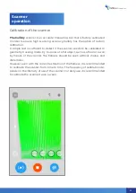
To start 

the scan session in the preview 

mode, press the button at the bottom 
of the screen. 
For convenience, you can also use the 
mechanical button located under the 
screen.

To finish 

the scan session, click the 

button at the bottom of the screen. 
For convenience, you can also use the 
mechanical button located under the 
screen. 

Upon finishing the scan session, the scanner shifts to the preview mode.

3D scanner

13

Summary of Contents for Calibry

Page 1: ...3D scanner User manual...

Page 2: ......

Page 3: ...surfaces This guide provides information on how to install and use Calibry software how to operate the scanner and recommendations for the scanning process itself When using the device keep in mind t...

Page 4: ...Front panel Scanner hardware device Geometric camera Projector Texture camera Texture flash User manual 2...

Page 5: ...Rear panel Scanner hardware device Touch screen Button START Scanner data cable connector Button STOP 3D scanner 3...

Page 6: ...case will not be covered under the warranty When the scanner is powered on it turns on automatically When you first connect the scanner to the computer we recommend that you connect the computer to t...

Page 7: ...el is used to display the sidebar Here you can also specify the name of the current project the object being scanned by clicking on the title in the centre All scanned parts of the object will be plac...

Page 8: ...operation The sidebar presents information on the available and occupied space on the hard disk of the computer to which the scanner is connected as well as buttons for scanner settings and the scann...

Page 9: ...re sorted by crea tion date the newer the higher Scans can also be grouped in their respective project sections At any time you can switch to another project by click ing on the section bar or create...

Page 10: ...scan in the project can be deleted by simply swiping the item in the list sideways You can cancel the deletion within 5 seconds by clicking the Cancel button You can delete all scans by clicking the D...

Page 11: ...by markers With tracking by texture The preview mode allows you to select the correct scan angle to determine the optimal distance to assess the nature of the surface to set up the scan pa rameters an...

Page 12: ...mprove texturing Increase the setting value to decrease the number of texture frames in the project In some cases this can improve texturing as well And in any case this will reduce the project volume...

Page 13: ...e scanner screen so you can visually assess the texture quality in advance Set the parameter value so that the texture is displayed in the best quali ty Before scanning in preview mode analyze the tex...

Page 14: ...mended for scanning shiny objects The default mode is average capacity Set this parameter to one of the following values To select the maximum average or minimum texture flash capacity respec tively S...

Page 15: ...For convenience you can also use the mechanical button located under the screen To finish the scan session click the button at the bottom of the screen For convenience you can also use the mechanical...

Page 16: ...lose to optimal If the scanning distance is too small the object is tinted with the colours from the lower part of the spectrum yellow orange red If the scanning distance is too large the object is ti...

Page 17: ...If there are not enough markers in the frame less than three the scanning will automatically stop and the scanner will return to the preview mode Then you should find a more comforta ble position to s...

Page 18: ...in geometry or marker tracking mode is not possible When scanning in texture tracking mode a textured image is displayed on the scanner screen To maintain the correct scanning distance use the scale...

Page 19: ...eds to be calibrated In geometry tracking mode try to look at a flat object such as a floor or a wall by means of the scanner The flatness should be seen without holes and distortions However even wit...

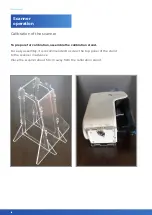
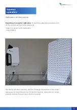
Page 20: ...ation To prepare for calibration assemble the calibration stand For easy assembly it is recommended to screw the top panel of the stand to the scanner in advance Place the scanner about 50 cm away fro...

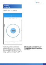
Page 21: ...ocedure turn on the scanner and go to the side panel Select Scanner and Calibration Click START The device will start scanning and the message will appear on the screen asking you to move the scanner...

Page 22: ...t and right until the smaller of the two red circles aligns with the black circle of the same size 3 Move the scanner stand slightly to the left and right until the large red circle aligns with the bl...

Page 23: ...know how much the scanner should be moved As soon as the software finishes the calibration in the second position it will move to the third one the fourth one etc There are seven positions in total On...

Page 24: ......

Page 25: ...3D scanner Software manual...

Page 26: ...Tray Manager This module is designed to provide the scanning pro cess and to acquire raw data Calibry Nest This module is designed for raw data postprocessing and sav ing of the obtained 3D model in...

Page 27: ...memory size of 2048Mb RAM size 16 GB minimum USB 3 0 Installation and First Startup To install the software onto your laptop or computer launch the msi file in cluded with your scanner and follow the...

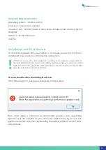
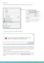
Page 28: ...ottom corner the Calibry Tray Manager icon will appear In order to switch the default graphics card follow the instructions below If during startup this error message is displayed Right click on deskt...

Page 29: ...nections have been made Otherwise the scanner could be damaged and in this instance a defect is not considered under warranty Calibration File Each Calibry scanner is supplied with a calibration file...

Page 30: ...Start by Connect automatic module startup when scanner connection is detected Start by Button automatic module startup when the Start button is pressed on the scanner Startup with System automatic mod...

Page 31: ...ll be opened for postprocessing Right click the scan list to activate the pop up menu Open folder click to select a folder where scans will be saved Refresh update the scan list A status bar is locate...

Page 32: ...data from scanning represents a set of frames captured by the scanner and used for 3D model building Most of the frames are geometrical Each geometric frame contains a certain number of points on the...

Page 33: ...extension also called a project file Opening a Project File To begin working with a project you should open it using one of the following methods 1 Click Open project in the toolbar and select projec...

Page 34: ...lick a project heading line with its name the visualization win dow displays a cloud of points formed by one in ten frames from the pro ject To visualize a full cloud of points click the Frames line l...

Page 35: ...ient when an object can be scanned from all directions without changing its position Scanning a human being is a typical example of this In general simple postprocessing includes three stages 1 Regist...

Page 36: ...pecifying the corresponding setting This procedure will automatically re move those points from the cloud that will be determined by the algorithm as noise or other data not relevant to the object bei...

Page 37: ...of the face of elementary polygons triangles which will constitute a polygonal model The smaller the size of an elementary polygon the more detailed a model is However in creasing the level of detail...

Page 38: ...The result of running the algorithm with a low resolution 4 mm The result of running the algorithm with a high resolution 0 7 mm 36 Software manual 36...

Page 39: ...on stage All holes can be filled on the 3D model Fill holes all Also only smaller holes can be filled when their radius does not exceed a certain value Fill holes Radius __mm In this case it is assume...

Page 40: ...s the appearance of the polygon mesh At a low level of sharpness the polygons are merged more smoothly without sharp angles while high sharpness makes geometry more detailed and thus the image becomes...

Page 41: ...tomatically identifies all markers on the surface removes them and fills newly formed holes If markers are in areas of the surface with nonuniform geometry the holes may be filled incorrectly Therefor...

Page 42: ...the corresponding height and radius of the basement in millimeters Floor detection The procedure automatically recognizes and cuts the floor surface Cut height is counted from the floor and is specif...

Page 43: ...ces in the simplified mesh specifies the extent of ge ometry simplification Example if the initial model has 1 000 000 polygons then reducing it to 20 of the original will yield a model which consists...

Page 44: ...esolution Fill holes Sharpness 2 1 Removing markers Marker size 2 2 Filtration by size Leave the biggest part Remove all parts smaller than 2 3 Floor detection 2 3 1 Basement creation 2 4 Remeshing Tr...

Page 45: ...ould have common points This must be taken into account during scanning If two parts of one object do not have intersecting areas it is impossible to align these parts You cannot align textured parts...

Page 46: ...to which all oth er parts of object will be aligned to 2 Alignment window Here the part of the object is displayed that is aligned to the base in current iteration 3 Result window Here the result of...

Page 47: ...window just like in the result window We need to stick the remaining third part to this model To do this left click it in the scan list window Meshes for alignment The third part of the object will a...

Page 48: ...f the object can be added to the base model in a similar way until all of them stick to the base When all parts are aligned together click Accept Changes The complete point cloud of an aligned model w...

Page 49: ...ing procedure be sure to select the projects from which final 3D model is assembled Data from projects not marked by tick will not be used in multiple postprocessing procedures Manual alignment If obj...

Page 50: ...nel or deleted These tools are availa ble to correct issues that might have occurred during scanning For example when scanning a human being even a small difference in facial expression can lead to a...

Page 51: ...eview frames from bottom to top starting from the last From a certain moment approximately from Frame 4050 the leg starts to split Therefore wecanconcludethatinframes 0 4050thelegsurfaceismapped corre...

Page 52: ...down menu Then try to assemble the 3D model with parts from several projects In the context of relevant example it is possible to try to divide the project into two parts 0 4050 and 4051 4455 If split...

Page 53: ...cursor was moved but on all surfaces under it In the above example for the left hole the surface area has been selected by the conventional Marquee Brush therefore the hole was formed in that part of...

Page 54: ...d by the algorithm on the 3D model surface is displayed in the project tree In the visualization window holes on the model will be highlighted by a green color When corresponding holes are selected in...

Page 55: ...3D scanner 53...

Page 56: ...ears Luminosity brush This is a tool for textured model processing Move the cursor over the model surface to increase texture brightness To decrease brightness e g to delete glare from flash move the...

Page 57: ...del Interface The interface tab enables editing of user interface settings and includes the following settings Surface front color color of polygonal model surface Surface back color color of polygona...

Page 58: ......

Page 59: ...User manual DRAKE...

Page 60: ...indow appears on the screen The main window will contain Status Bar Control Panel Side Panel List of scans if any Main Thumb Control Buttons Status Bar The status bar will display the current status o...

Page 61: ...calibration number and calibration version On the bottom of the panel there is a safe off button To properly turn the scanner off press and hold this button for two seconds For a hard reboot you may a...

Page 62: ...screen or by creating a new project by naming it on the control panel above You can use any USB drive Flash HDD to save your projects preferably however they should be formatted for the NTFS file syst...

Page 63: ...r is controlled via touch screen Use your right hand thumb while the rest of the hand supports the scanner The main buttons are conveniently located on the right side of the screen and can perform the...

Page 64: ...surface is blue you are getting too far from the object If it is red the scanner is in danger of being too close The op timal distance is shown in green so try to keep the scanner at that distance to...

Page 65: ...iew the indicator will turn red the value is critically low and tracking might be lost If 5 markers are in view the indicator is yellow warning If more than 5 markers are in view green all is good Sca...

Page 66: ...he textures off Reconstruction Sensitivity If during scanning there is a lot of noise on the screen that means that either the object is very dark black objects are gen erally more difficult to scan t...

Page 67: ...If the object is black use If the object is white use The default value of the color mode is Scanner operation Circular LED flash capacity Flash Indicator There are three modes for the power of the ci...

Page 68: ...re or less bright This proves especially useful for scanning humans as this setting helps achieve the most natural looking texture You also might like to leave the default value and instead adjust bri...

Page 69: ...icator signal strength will appear in the status bar Aside from a Wi Fi USB adapter you can also be using an Ethernet USB adapter to connect to a local network Find the scanner under Network on any co...

Page 70: ...eparation for calibration To calibrate the scanner unpack the calibration stand and assemble it Attach the pole to the base Attach the correct board to the base and the pole Ease the scanner into the...

Page 71: ...ds to be aligned in three ways 1 Find the correct distance to the calibration board by moving the stand with the scanner closer and further from it The indicator on the left side of the screen will il...

Page 72: ...finished the screen will prompt for second position Move the scanner slowly away from the board and watch the distance indicator for guidance as to how far to move Once the software finishes calibrati...

Page 73: ...e approximately 18cm 7in away from the board Drake MIDI will use the medium board and its starting position will be at approximately 32cm 12in away from the board Drake MAXI needs the largest calibrat...

Page 74: ...72 Drake User manual 72...

Reviews: