20
Heat Mode
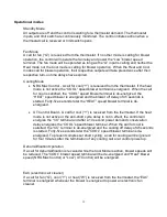
When a call for heat (“W”) is received from the thermostat, if the “Cool” mode is not
already active, the “T-T” terminal is energized and the blower on delay is started. When
the delay time the “HEAT” blower speed is energized. The control remains in steady heat
mode until the thermostat is satisfied. When the call for heat signal is removed, the “T-T”
terminal is de-energized and the blower off delay is started. When the delay time has
elapsed, the “HEAT” blower speed terminal is de-energized.
Blower On and Off Delays (Heat Mode Only)
Four Heat blower on and four blower off delays are selected by two dip switches for each
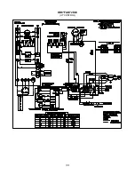
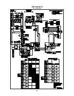
function. Refer to wiring diagrams Appendix B for specific delay values.
Motor Blower Speed
Three interconnected blower speed outputs are provided. A “G” call for fan will provide
power to the LOW speed tap only. A “W” heat call will provide power to the Heat speed
tap only. A “Y” cooling call will provide power to the Cool speed tap only. The speed taps
are interconnected and interlocked; only one speed may be powered at any one time.
Counterflow Operation
NRG Max Control - Counterflow operation will only be allowed if “Options”
Counterflow switch is in the ON position
UT Control Board - Counterflow operation will only be allowed if JW10 is cut.
Counterflow Operation is only valid when a call for Heat is present. Counterflow
Operation will bring the blower on at the “LOW” speed at a defined time between the
enabling of the burner and the selected turn on time delay. Turn on delay times for the
Counter Flow Operation is defined in Table 3. Once the selected Blower On Delay time
has been reached, the blower operation will change to the operation described in Heat
Mode section.
BLOWER ON DELAY DIP SWITCH SELETION
COUNTERFLOW
BLOWER ON DELAY
2
1
OFF
OFF
15 Sec.
OFF
ON
24 Sec.
ON
OFF
36 Sec.
ON
ON
48 Sec.
Table 3: Counterflow Blower On Delay
Advanced Features (NRG Control only)
Tank Level, Refrigerant Temperature and Duct Sensor connections are for future use
with a third party cloud based service called Aviexx. Contact Aviexx.com for more
information.
Summary of Contents for OD6FA072D48
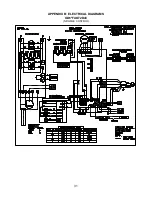
Page 32: ...31 APPENDIX B ELECTRICAL DIAGRAMS OD6 FAO72D48 NRGMAX CONTROL...
Page 33: ...32 OD6 FAO72DV5 NRGMAX CONTROL...
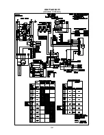
Page 34: ...33 OD6 FAO72D48 UT CONTROL...
Page 35: ...34 OD6 FAO72DV5 UT CONTROL...
Page 37: ...36 APPENDIX D REPLACEMENT PARTS OD6FA072D48 OD6FA072DV4...
Page 38: ...37...
Page 39: ...38 OD6RA072D48 OD6RA072DV4...
Page 40: ...39...
Page 41: ...40...
Page 42: ...41...
Page 43: ...42...


