Cinterion
®
MV31-W Hardware Interface Description
5.3 Thermal Design Guidelines
75
t
MV31-W_HID_v01.009a
2022-04-27
Public / Preliminary
Page 47 of 76
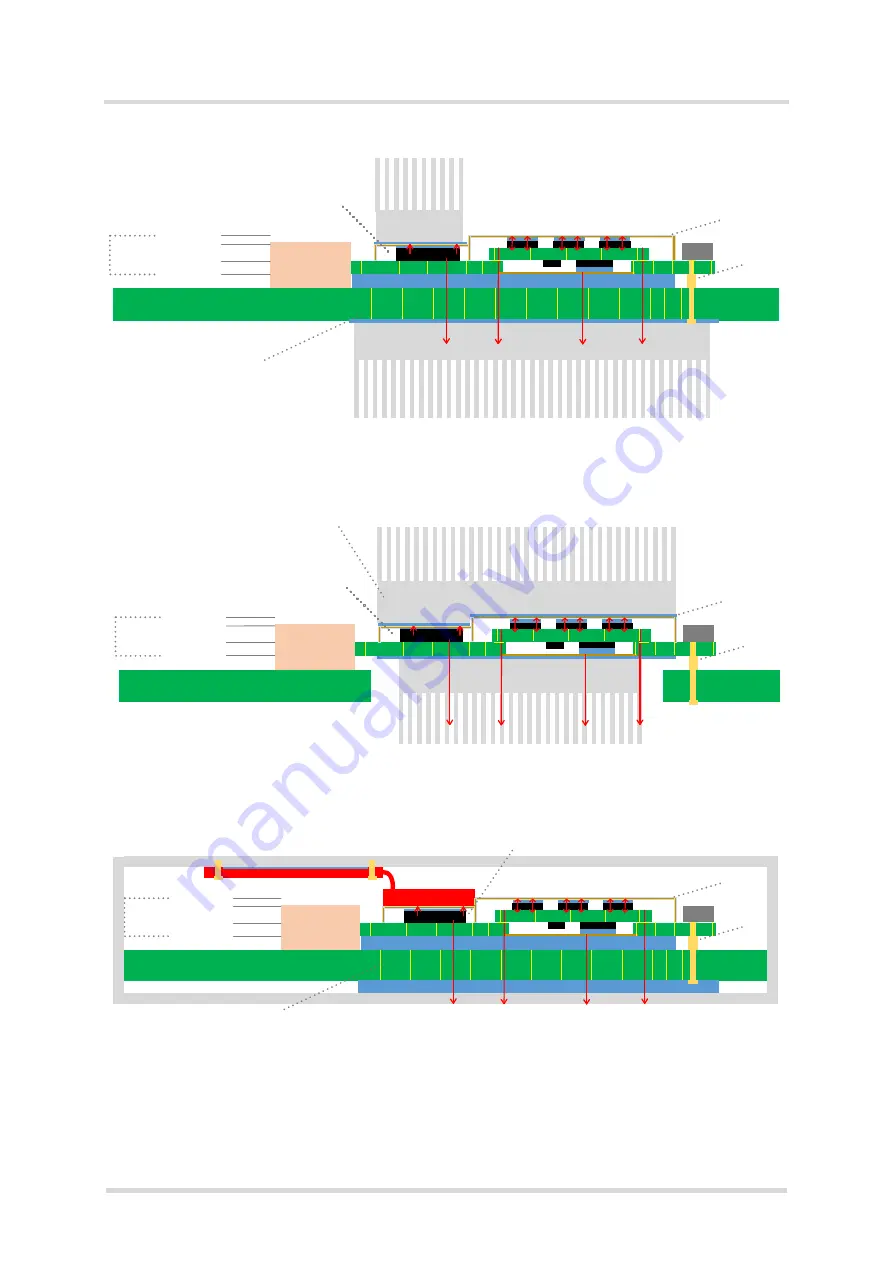
Figure 21:
Option 2 - Heat sink only on heat spot of stepped shielding and bottom of application PCB
Figure 22:
Option 3 - Heat sink on top of stepped shielding and directly on bottom of M.2 card PCB
Figure 23:
Option 4 - Heat pipe and small application housing
Application/ System PCB
(typ. 1.6mm)
Heat sink
Heat sink
M.2 PCB
(0.8mm)
M.2 CON
H2.3 S5
(Typ 2.25mm)
TIM
(typ. 0.3mm)
RF PCB
IC
IC
IC
0.8mm M.2 PCB
+1.3mm Shield
+0.5mm Shield
2.6m
m
to
ta
l
he
ig
ht
Screw
CON
IC
Shield
Heat spot of th e M.2 card is below
the lower shield. Allows internally
thinner TIM with lower Rth
Recommended to use GND
planes stiched with vias for
better thermal performance
Application/ System PCB
(typ. 1.6mm)
Heat sink
M.2 PCB
(0.8mm)
M.2 CON
H2.3 S5
(Typ 2.25mm)
RF PCB
IC
IC
IC
0.8mm M.2 PCB
+1.3mm Shield
+0.5mm Shield
2.6
m
m
to
ta
l
he
ig
ht
Screw
CON
IC
Shield
Stepped heat sink to allow
thinner TIM => better Rth
Heat sp ot of th e M.2 card is below
the lower shield. Allo ws internally
thinner TIM with lower Rth
Heat sink
Application/ System PCB
(typ. 1.6mm)
M.2 PCB
(0.8mm)
Heat pipe
M.2 CON
H2.3 S5
(Typ 2.25mm)
TIM
(typ. 0.3mm)
TIM
RF PCB
IC
IC
IC
0.8mm M.2 PCB
+1.3mm Shield
+0.5mm Shield
2.
6
m
m
to
ta
l
he
ig
ht
Screw
CON
Recommended to use GND
planes stiched with vias for
better thermal performance
Heat pipe
IC
Shield
Heat spot of the M.2 card is below
the lower shield. Allo ws internally
thinner TIM with lower Rth
Housing


