

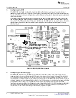
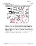


Configuring the Power Supply
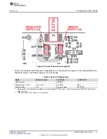
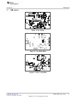
Figure 3. Power Terminals and Jumpers
Table 2 summarizes the EVM power configurations to connect and route power to the onboard LDOs and
LMK61E2. Refer to the EVM schematic for more details.
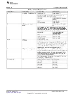
Table 2. Power Configurations
MODE
EXTIN VOLTAGE
J2 SETTING
(1)
J3 SETTING
(1)
USB Powered
(2)
USB PWR
External Power + LDO
4.3 V to 5.5 V
EXT PWR
REG
External Power
3.3 V
Remove Jumper
EXT PWR
(1)
Markings left of J2 indicate the orientation of jumper settings EXT PWR (pins 1 and 2 of jumper) and USB PWR / REG (pins 2
and 3 of jumper)
(2)
USB cable must be connected to J1 for operation
7
SNAU188 – October 2015
LMK61E2EVM User's Guide
Copyright © 2015, Texas Instruments Incorporated


