


OUT_P
0.1µF
C25
0.1µF
C24
0
R25
0
R28
OUT_N
R_OUT_P
R_OUT_N
1
2
3
4
5
P2
OUTP
1
2
3
4
5
P3
OUTN
0
R27
100
R31
0
R30
150
R26
150
R29
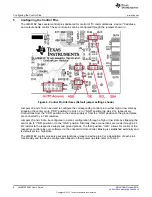
Configuring the Clock Output
6
Configuring the Clock Output
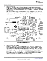
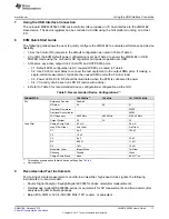
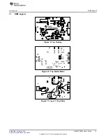
The LMK61E2’s differential output is routed via 50 ohm single ended traces to SMA ports (OUTN and
OUTP) through AC coupling capacitors. The output also has a series resistor (0 ohm populated by default,
R25 ad R28) and emitter resistors (150 ohm populated by default for LVPECL, R26 and R29). Common
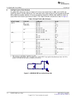
output format terminations are shown in Table 4. The output termination schematic is shown in
.
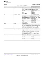
Table 4. Output Termination Schemes
OUTPUT FORMAT
COUPLING
COMPONENT
VALUE
LVPECL
AC
R25, R28
0
Ω
(default EVM
R26, R29
150
Ω
configuration)
C24, C25
0.01 uF
R27, R30, R31
DNP
DC
(1)
R25, R28, C24, C25
0
Ω
R26, R27, R29, R30, R31
DNP
LVDS
(2)
AC
R25, R27, R28, R30
0
Ω
R31
100
Ω
C24, C25
0.01 uF
R26, R29
DNP
DC
R25, R27, R28, R30, C24, C25
0
Ω
R31
100
Ω
HCSL
AC
R25, R28
0
Ω
(22
Ω
optional)
R26, R29
50
Ω
C24, C25
0
Ω
R27, R30, R31
DNP
DC
R25, R28
0
Ω
(22
Ω
optional)
R26, R29
50
Ω
C24, C25
0.01 uF
R27, R30, R31
DNP
(1)
50 ohm to Vcc-2 V termination is required on receiver.
(2)
100 ohm differential termination (R31) is provided on the LMK61E2EVM. Removing the differential termination on the EVM is
possible if the differential termination is available on the receiver.
Figure 5. LMK61E2EVM Termination Schematic
10
LMK61E2EVM User's Guide
SNAU188 – October 2015
Copyright © 2015, Texas Instruments Incorporated


