

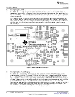
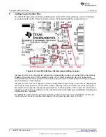
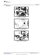
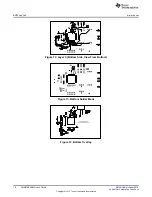


Configuring the Control Pins
Table 3. Control Pin Interfaces
COMPONENT
NAME (TYPE)
DESCRIPTION
DESCRIPTION
J5
OE (passive or software control)
Output Enable Pin
Output Enable Pin
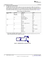
OE state controls the device output operation. Polarity can be
adjusted in the LMK61E2’s register settings.
OE STATE
OPERATING MODE (based on
default)
GND
Output Disabled
VDD (JP Default)
Output Enabled
J6
ADD (passive or software
I
2
C Slave Address LSB Select
control)
pin
ADD is sampled on POR to configure the lower 2 bits of the 7-bit
slave address. The upper 5 bits of the slave address are initialized
from EEPROM (SLAVEADR[7:3] = 10110b). By configuring ADD, the
composite slave address can be selected as follows:
ADD STATE
7-BIT SLAVE ADDRESS
(excludes W/R bit)
GND
1011000b / 0x58
High Z (no connect)
1011001b / 0x59
VDD (JP Default)
1011011b / 0x5B
J9 J10
SCL SDA
I
2
C Serial Interface Pins
(I
2
C inputs)
An I
2
C master device can interface with the LMK61E2 over the I
2
C
clock line (SCL) and data line (SDA). The open drain topology of the
SCL and SDA pins require an external pull up resistor. J9 and J10
should always be set in the VDD position to ensure proper I
2
C
communication. The SCL and SDA lines are connected with the
onboard microcontroller, which is controlled by the GUI.
J1
USB (not shown in Figure 4)
USB port (Mini-B type)
USB port (Mini-B type)
Using the GUI platform, USB controller (U4) provides the USB-to-I
2
C
interface to manage the LMK61E2 device registers and EEPROM.
When USB communication is established with a Host PC running the
GUI, LED D5 should be lit solid green.
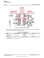
The USB port powers LDO regulator U1 to supply 3.3 V power for
the MCU and its peripheral circuitry.
J4 (not populated)
U2A
Optional Test Point Access to I
2
C and Control pins
Pin 1: SDA
Pin 2: SCL
Pin 4: N/C
Pin 3: N/C
Pin 5: GND
Pin 6: N/C
Pin 7: OE
Pin 8: ADD
Pin 9: N/C
Pin 10: N/C
9
SNAU188 – October 2015
LMK61E2EVM User's Guide
Copyright © 2015, Texas Instruments Incorporated


