


Configuring the EVM
3
Configuring the EVM
The LMK61E2 is a highly-configurable crystal oscillator with simple power supply requirements and
flexible clock output formats. To support a wide range of evaluation use cases, the EVM was designed for
maximum flexibility so various configurations options that are not required in all typical system applications
have been included.
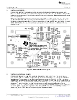
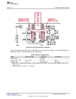
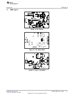
This section describes the jumpers and connectors on the EVM, as well as how to connect, set-up, and
use the LMK61E2EVM. When operating the LMK61E2EVM, the power supply and clock outputs can be
connected to the SMA ports shown in Figure 2. Additionally, the USB port can be used to power the entire
LMK61E2EVM without the need for external power supplies. These SMA ports are labeled in the top
silkscreen layer.
Figure 2. LMK61E2EVM Board Layout
4
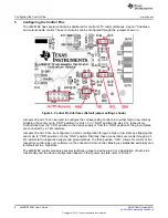
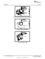
Configuring the Power Supply
The LMK61E2 features a single VDD supply pin that operates from 3.3V (+ 5%). This supply can be
powered directly from an external supply or through an on-board LDO regulator. Although the LMK61E2
has integrated LDO regulators for excellent power-supply-ripple-rejection (PSRR), the EVM’s on-board
regulator (U2) can allow a higher supply voltage (like 5 V) to power the EVM. The direct external supply or
on-board regulator can be independently routed for the VDD supply pin by configuring the power terminals
and jumpers shown in Figure 3. J1 (USB mini connector) is the default power supply for the EVM,
featuring a low noise regulator for voltage step down. Power SMA Port EXTIN (P1) provides an alternative
connector style to apply power using coax cables. Using EXTIN while connected to USB power is not
required but can be useful when testing with externally regulated supplies.
6
LMK61E2EVM User's Guide
SNAU188 – October 2015
Copyright © 2015, Texas Instruments Incorporated


