Configuring the Control Pins
5
Configuring the Control Pins
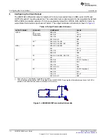
The LMK61E2 has several control pins dedicated for control of I
2
C communications, device I
2
C address,
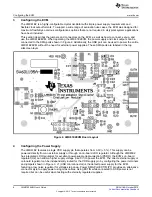
and output enable control. These control pins can be configured through the jumpers shown in .
Figure 4. Control Pin Interfaces (Default jumper settings shown)
Jumpers J9 and J10 can be used to configure the corresponding control pin to either high or low state by
strapping the center pin to “VDD” position (tie pins 1-2) or “GND” position (tie pins 2-3), respectively.
Connections from the “VDD” position to the device supply or from the “GND” position to the ground plane
are connected by 4.7 k
Ω
resistors.
Jumpers J5 and J6 can be configured in a static configuration through a high or low state by strapping the
center pin to “VDD” position or to the “GND” position. Similarly, these connections are made through a 4.7
k
Ω
resistor to the respective supply and ground planes. The third position, “U2A”, allows for control of the
respective control pins over software via the onboard microcontroller. Biasing is established externally and
is default set to a high state.
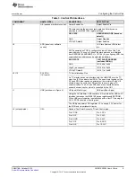
The LMK61E2 control pins serve several functions unique to device pins. For a description of each pin’s
functionality and the device configuration based on their power up state, refer to Table 3.
8
LMK61E2EVM User's Guide
SNAU188 – October 2015
Copyright © 2015, Texas Instruments Incorporated


