33
Melody 2 Hydraulic MK2 Installation Manual - Issue f
Dϭ
Ϯϰs
E
>K<
dDZϭ
K
>K<
dDZWtZ
W
dDZKͬW
h
>Kt
'd^K>
y
ϭϰϲϲ
dϱKKZ
;dƌĂŝůŝŶŐĂďůĞͿ
z
ϵϲϲdϯ
KKZ
hWWZ
KKZ^K>
DϮ
hWWZ
Z'd
^t
Dϯ
>>^dE
'dhddKE
&
Dϰ
>>^dE
'dhddKE
&
Z
>Kt'd
E>^t
&
^
hWWZ'd
E>^t
&
d
>Kt'd
E>^t
ZdhZE
s
hWWZ'd
E>^t
ZdhZE
t
hWZ
dϮZ
;dƌĂŝůŝŶŐ ĂďůĞͿ
>Kd/E>/&dWKtZW<
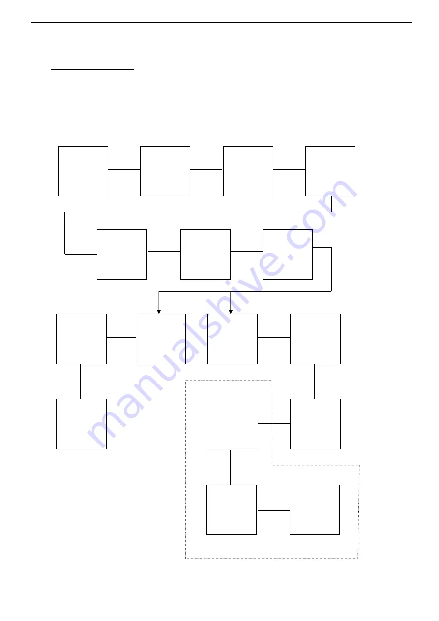
Door Enable Circuit
The following flow chart highlights the route of the Door Enable Circuit. The
timer controlling the door locks originates from the same timer. Letters relate
to check poins on pages 31& 32.
Summary of Contents for Melody 2 hydraulic MK2
Page 35: ...35 Melody 2 Hydraulic MK2 Installation Manual Issue f FIG 3 CARRIAGE WIRING...
Page 36: ...36 Melody 2 Hydraulic MK2 Installation Manual Issue f FIG 4 CONTROL SYSTEM COMPLETE WIRING...
Page 42: ...42 Melody 2 Hydraulic MK2 Installation Manual Issue f...
Page 48: ...48 Melody 2 Hydraulic MK2 Installation Manual Issue f...
Page 50: ...50 Melody 2 Hydraulic MK2 Installation Manual Issue f...
Page 54: ...54 Melody 2 Hydraulic MK2 Installation Manual Issue f...
Page 58: ...58 Melody 2 Hydraulic MK2 Installation Manual Issue f ED20431 23 08 2011 Bulletins...
Page 60: ...60 Melody 2 Hydraulic MK2 Installation Manual Issue f...


