ISU-689:2016/GB
7
3.6. Selection of expansion vessel
The boiler is not equipped with an expansion vessel, the vessel must
be mounted on the installation. In installation with additional
hydraulic coupling or plate heat exchanger, an individual expansion
vessel should be installed in the boiler
’s
circuit. A proper expansion
vessel should be selected by the designer of central heating system.
Installation of expansion vessel should be made by an installation
contractor in accordance with applicable regulations.
3.7. Condensate outlet
Each boiler has a condensate drainage system installed and already
connected.
The flexible pipe for condensate drainage must be connected to the
condensate collection and removal system in accordance with the
applicable regulations. The designer, considering the power of the
installation and the utility of the building, should adapt the system to
neutralization of the resulting condensate. The condensate drain
installation must be made of corrosion-resistant material.
The installation should be carried out in a way that prevents the
condensate from freezing. Check the condensate drain before
starting.
The connection of drain the condensation water cannot be
blocked.
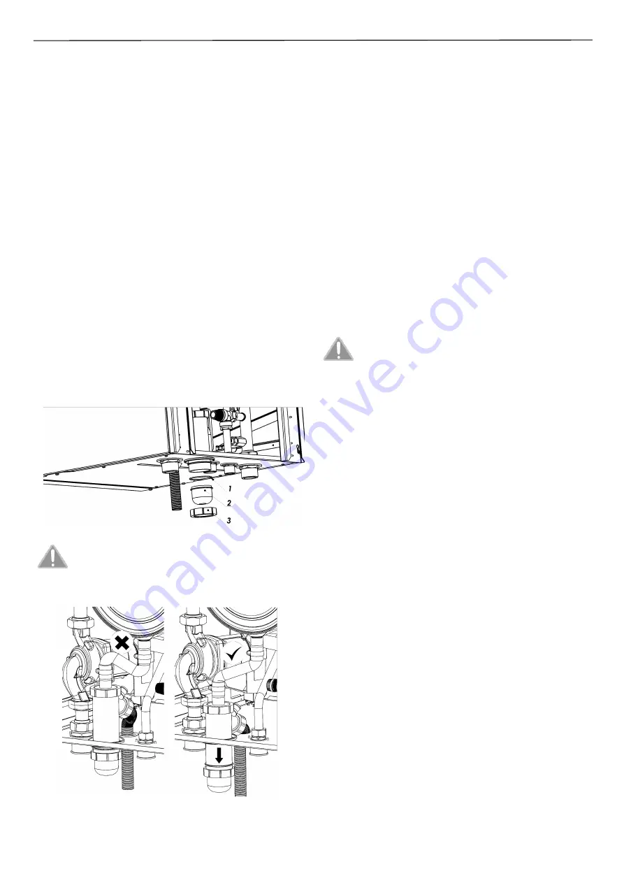
The bottom of the siphon (2) was dismantled during transport. All
parts necessary for installation: 1-gasket, 2-bottom of siphon, 3-nut,
are in the package of the boiler. Before starting the boiler, the siphon
should be assembled in accordance with Fig. 3.7.1.
Fig. 3.7.1
–
Mounting the siphon
Before the start-up of the boiler move the siphon to the
lowest position, to enable the hose (which connect heat
exchanger with siphon) to a proper condensate outlet
(see the Fig. below). A bent hose may cause the flooding of
heat exchanger by produced condensate.
During the start-up or after a long downtime, make sure that the
condensate is properly drained through the drain (E) see Fig 3.4.1.
3.8. Flue gas outlet
Flue gas outlet from the boiler must be made in accordance with
applicable regulations and this instruction manual and it needs to be
agreed with the district chimney sweep service company.
For flue systems, the boiler is made according to type: C13, C33, C43,
C63, B23.
•
it has closed combustion chamber in relation to the room where it
is installed (C),
•
is adjusted to be connected to separately approved and marketed
air-flue gas systems,
•
it is equipped with a blowing fan (3).
The boiler is designed for cooperation with the flue gas
–
air system
with a diameter of
Φ
100 (flue gas and air) and in a collective
cascade system where the flue gas exhaust from a single boiler is
realized by a pipe with diameter of
Φ
100. To install the flue gas
–
air
system to the boiler, it is recommended to mount the flue gas
adapters according to this manual, the adapters are supplied with
the boiler and are added to the boiler
’s
package.
Other components of the flue gas
–
air system of the boiler should be
purchased according to the design of the installation.
The boiler is factory adjusted with mounted exhaust
pipe
Φ
100 of the maximum length 0,5m without air
pipe. Settings CO
2
–
9% for natural gas. To use the other
systems and longer pipes it is required to adjust the
boiler as specified in point 4.3.
Connections and chimney duct must be designed and constructed in
accordance with applicable regulations. They must be made of
suitable material. They also must be corrosion-resistant, smooth
inside and tight, impervious to condensate.
Use the appropriate wire size (diameter, maximum length, resistance
on the knees), depending on the combustion system used. The
dimensions of the wires should be adequately compatible as given in
table. Resistance of flue gas flow on each elbow depending on the
bending angle and related reduction of the maximum wire length are
given in section 3.8.2.
Connection of the boiler to the air-flue gas system and installation of
the system itself should be sealed. Each system should be installed
with the windproof outlet protecting against external factors.
Before turning on the boiler check if flue-gas system is made
according to the project and air- and flue ducts lengths are shorter
than maximum lengths showed in above tables. Make sure flue-gas
system is tight.
After turning on the boiler check if it operates correctly. Also check
combustion parameters by checking concentration of CO
2
and/or O
2
in flue-gas.
3.8.1. Configuration Type B with open chamber and forced
draft
The air is sucked directly from the environment in which the boiler is
installed through the hole made in the boiler
’s
top cover. The
exhaust outlet should be connected to your own single chimney or
directed directly to the outside of the building according to the
requirements of applicable regulations.
Boilers with open combustion chamber type B can not be installed in
rooms exposed to vapors or volatile substances (e.g. vapors of acids,
paints, adhesives, solvents, fuels, etc.), as well as areas dusty with
wood, coal, cement, etc.


