MAINTENANCE
186 MM159 (6–94)
3Ć44
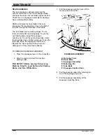
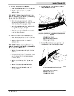
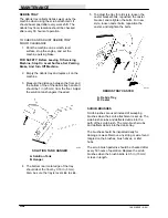
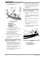
3. Pull the squeegee suction hose off the
recovery tank connector.
A
B
C
D
E
E
F
03162
SQUEEGEE ASSEMBLY
A. Recovery Tank
B. Drain Hose
C. Squeegee Assembly
D. Retaining Pin
E. Side Bolts
F. Squeegee Suction Hose
4. Pull the squeegee assembly retaining pin
out of the squeegee pivot pin.
5. Pull the squeegee assembly off the
squeegee mounting block.
TO INSTALL SQUEEGEE ASSEMBLY
1. Place the squeegee lever in the up position.
2. Stop the engine and set the machine
parking brake.
FOR SAFETY: Before Leaving Or Servicing
Machine; Stop On Level Surface, Set Parking
Brake, And Turn Off Machine.
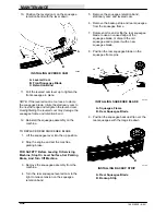
3. Slide the squeegee assembly onto the
squeegee mounting block. Be sure the side
bolts are above the squeegee frame.
4. Slide the squeegee assembly retaining pin
through the squeegee pivot pin.
5. Push the squeegee suction hose onto the
recovery tank connector.
TO REPLACE FRONT SQUEEGEE BLADE
1. Place the squeegee lever in the up position.
2. Stop the engine and set the machine
parking brake.
FOR SAFETY: Before Leaving Or Servicing
Machine; Stop On Level Surface, Set Parking
Brake, And Turn Off Machine.
3. Remove the squeegee assembly from the
machine.
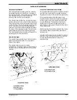
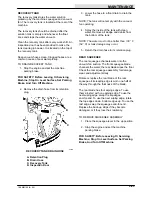
4. Turn the front squeegee levered cam to the
right to relieve tension on the squeegee
retention band.
5. Remove the stationary cam and levered
cam.
6. Remove the squeegee retention band.
7. Remove the front squeegee from the
squeegee frame.
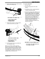
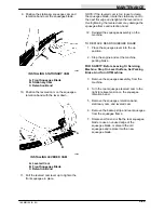
8. Position the new front squeegee blade on
the squeegee frame pins.
A
C
B
00927
INSTALLING FRONT SQUEEGEE BLADE AND
BAND
A. Retention Band
B. Front Squeegee Blade
C. Squeegee Frame
Summary of Contents for 186
Page 1: ...186 MM159 Rev 05 12 95 Operator Manual ...
Page 10: ...SPECIFICATIONS 186 MM159 6 94 1Ć2 ...
Page 14: ...OPERATION 186 MM159 6 94 2Ć2 ...
Page 84: ...MAINTENANCE 186 MM159 6 94 3Ć48 ...
Page 86: ...APPENDIX 186 MM159 6 94 4Ć2 ...
Page 88: ...APPENDIX 186 MM159 6 94 4Ć4 ...

