INSTRUMENT MANUAL
VACUUM GAUGE MODEL MM200
160Phone:(215) 947-2500 fax:(215) 947-7464 e-mail:[email protected] web site:www.televac.com
MM-200_im REV M
Page 138 of 160
TELEVAC
902 SETUP OF MODULE BOARDS
The module boards are preset at the Televac factory. However, if you wish to change them, first remove them from
the MM200 in accordance with the instructions in Section 308.
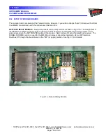
SETPOINT RELAY MODULE
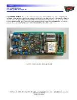
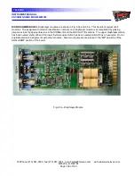
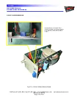
- A setpoint process control relay module is shown in Fig. 9.1a. The assignment of
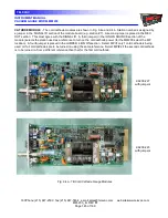
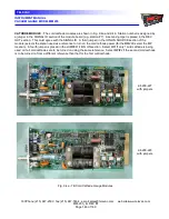
identification numbers for this module (usually done at the factory) is accomplished by placing jumpers on the
appropriate pins in the SETPOINT ID section of the module. Note that two (2) sets of jumpers are required. The
SIGNAL SOURCE section is used for the MM200 and jumpers should be installed in all four MP locations.
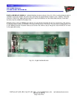
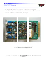
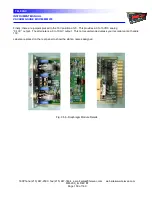
Switches S1 through S4 should be set in the "MP" (or upper) position. See Fig. 9.1b for details.
Fig. 9.1a - Setpoint Relay Module

