


INSTRUMENT MANUAL
VACUUM GAUGE MODEL MM200
160Phone:(215) 947-2500 fax:(215) 947-7464 e-mail:[email protected] web site:www.televac.com
MM-200_im REV M
Page 29 of 160
TELEVAC
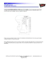
SETPOINT RELAY MODULE
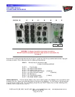
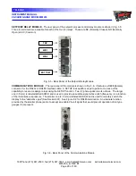
- The rear panel of the setpoint process control relay module is shown in Fig. 3.5.
Three (3) terminals are available for each of the four (4) relays. These are NC (Normally Closed), NO (Normally
Open) and C (Common).
Fig. 3.5 - Rear Panel of the Setpoint Relay Module
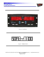
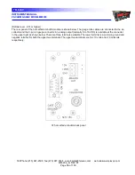
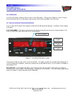
COMMUNICATIONS MODULE
- The rear panel of the module is shown in Fig. 3.6. It features a DE9S (female)
connector for the RS232 or RS485 interface cable. A SETUP lock switch is used to permit or to lock out the
capability to reset or reassign relays using the SETUP function. Two (2) phone jacks are also shown. The larger
one (3.5 mm) is labeled LEAK AUDIO and is used to provide an audible signal whose pitch (frequency) is a function
of the instantaneous pressure. The smaller one (2.5 mm) is labeled GAS SW and is used to remotely switch the
display to the "alternative gas" (See Section 401). See Figure 9.2 for RS485 termination. An alternate function
provided by the smaller phone jack is to accept an enable 24-volt signal that would prevent operation of ion type
gauges if not present.
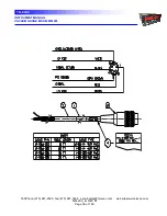
Fig. 3.6 - Rear Panel of the Communications Module
TOP
MID1
MID2
BOTTOM


