


INSTRUMENT MANUAL
VACUUM GAUGE MODEL MM200
160Phone:(215) 947-2500 fax:(215) 947-7464 e-mail:[email protected] web site:www.televac.com
MM-200_im REV M
Page 34 of 160
TELEVAC
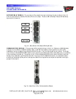
3E HOT CATHODE RESIDENT MODULE (EB DEGAS)
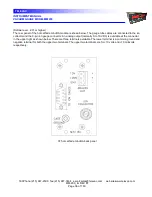
- The rear panel of the 3E hot cathode resident module
with electron beam (EB) degas is shown in Fig. 3.9. This module occupies 4 module slots. The module must be
within 10' (100' with a special cable) of the sensor (gauge tube). No station should be numbered higher than #5.
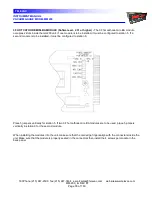
The sensor power and control cable is connected to the socket in lower right-hand side of the module. Push plug
straight in until the connector "clicks" into a locked position. To remove, press on the sides of the connector, until
the locks are released, and then pull straight out. The sensor ion collector cable is connected to the module via a
BNC connector located in the left-hand middle of the module. Push the mating connector in and twist clockwise to
secure.
Above the BNC connector is a case ground connection used to connect the unit independently to a "good earth
ground".
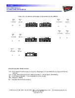
Below the BNC connector is a switch marked TUBE TYPE. Switch position with power off or turn power ON/OFF
after switching. See Table 3.4.
An analog output is available at the connector in the lower left of the panel. There are three terminals available.
The lower terminal is a common ground and negative terminal for both the upper two terminals. The upper two
terminals are for + 10 volts and + 10 millivolts respectively.
There is no filament selector switch for use with dual filament sensors on this unit as this is done through front
panel commands. It is necessary to switch the filaments when the filament power is off.
Refer to Section 502.3 Hot Cathode SETUP for further information.
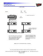
Fig. 3.10 Rear Panel of the Resident 3E Hot Cathode Gauge Module


