


INSTRUMENT MANUAL
VACUUM GAUGE MODEL MM200
160Phone:(215) 947-2500 fax:(215) 947-7464 e-mail:[email protected] web site:www.televac.com
MM-200_im REV M
Page 55 of 160
TELEVAC
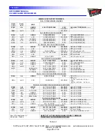
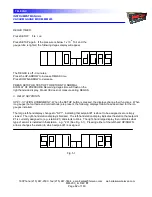
Pressing the TEST/OP button again causes the left-hand large display to show "Err". If there are no errors the
right-hand large display shows "none". Otherwise the right-hand large display shows one of the following,
depending on what error or errors have been found:
"Err
nonE"
There are no errors.
"P 15
HIGH"
The +15 volt supply is high.
"P 15
LO"
The +5 volt supply is low.
"P 5
HIGH"
The +5 volt supply is high.
"P 5
LO"
The +5 volt supply is low.
"-12
HIGH"
The -12 volt supply is high*.
"-12
LO"
The -12 volt supply is low*.
"ProG"
The program memory is faulty.
"Adc"
The A/D converter is faulty.
"Err"
FIL
shrt
no E
curr
HP
Shrt
Prty
Err
FrAn
G
Err
Shut dn
* High and low with respect to the negative supply refers to absolute value.
Pressing TEST/OP again causes the next fault to be displayed if there is more than one fault. After the last fault (or
"no err") is displayed, pressing the TST.OP button once returns the instrument to normal operation.
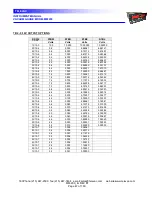
For software versions 2.03 and higher, pressing the TST/OP button twice in quick succession after the last fault, or
"no err", display will result in display of the 0-10V
output voltage formats for each installed sensor station with each
subsequent push. After the last recorder format is displayed, the next button push returns instrument to normal
operation. A complete listing of available 0-10V
output voltage formats with their display codes and corresponding
RS232 commands is shown in the following table on page 505A.
Across the bottom of the instrument is a door that pulls down to reveal those buttons, which are not normally used,
in the day-to-day operation of the instrument. The location of the numbered sensors and the assignment of relays
can be marked on the paper insert inside the door (See Fig. 2.2).


