


19-2233 PC2
2019-02-01
18(50)
ADQ7DC Manual
16-1796 PC2 2019-02-01
18(50)
The function on the digitizer has to be activated (armed) in reverse order compared to the data flow.
This means that one stage is set up to be prepared to receive data before the preceding stage is set up
to generate data. This is especially important in streaming applications where the DRAM FIFO may
overflow if the triggering is activated before the read-out to the host PC has started.
4.5 Trigger jitter
4.5.1
Trigger jitter definitions
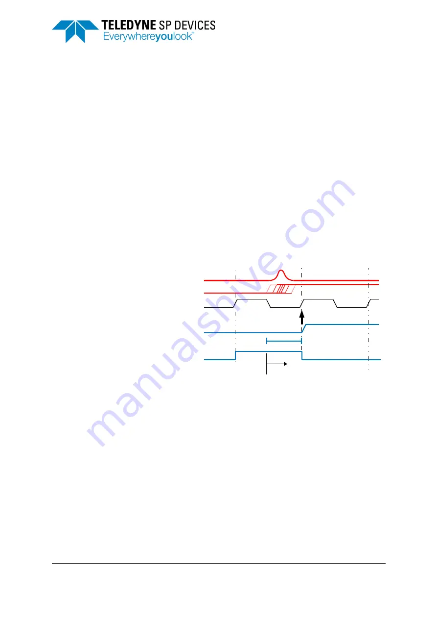
The triggering operation is subject to two different types of jitter,
.
1. At the trigger input is a Gaussian distributed jitter which affects the timing of the incoming trigger
signal edge. This jitter is called excess jitter and is caused by noise in the input stage. The RMS
value of this excess jitter is 25 ps.
2. The actual sampling process causes a timing uncertainty. Since the trigger is sampled with the trig-
ger clock, the time points for reading the trigger are discrete. The difference between the incoming
physical trigger signal and the digital representation of the trigger is a stochastic variable with a
rectangular distribution. The RMS value of such a process is
TRIGGER_CLOCK_PERIOD
/sqrt(12).
The highest resolution is achieved with an external trigger connected to the TRIG connector.
ADQ7DC has a trigger clock at 20 GSPS,
TRIGGER_CLOCK_PERIOD
of 50 ps and a trigger jitter of
14 ps RMS (theoretical value),
See
for time resolution all the external trigger sources.
4.5.2
Asynchronous triggering
If the trigger signal is not phase-locked to the reference clock it is called asynchronous. This trigger
does not have a well-determined relation to the sampling clock and will appear at various positions
within the sampling period. The time resolution of an asynchronous trigger connected to the TRIG input
is set by the Trigger Clock (20 GHz). The time resolution for other triggers is determined by the Data
Clock (312.5 MHz).
The asynchronous trigger will be exposed to both trigger sources from
. These indepen-
dent stochastic processes are added to 28 ps. See
for time resolution of all the external trigger
sources.
There are some advantages with the asynchronous trigger:
•
Any pattern noise will be reduced in repeated measurements.
•
The trigger resolution of 50 ps can be used for accurate timing calculations. The
TIME_STAMP
con-
tains the information about the trigger time. See
Figure 9: Sources of jitter on the trigger signal.
,
,
-./0/
/-
1
/
23%45!
6/


