


Overview of Operating Modes
Teledyne API – Model T300/T300M CO Analyzer
80
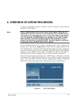
The mode field of the front panel display indicates to the user which operating mode the
unit is currently running.
Besides
SAMPLE
and
SETUP
, other modes the analyzer can be operated in are:
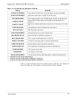
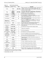
Table 4-1:
Analyzer Operating Modes
MODE
EXPLANATION
DIAG
One of the analyzer’s diagnostic modes is active (refer to Section 5.9).
LO CAL A
Unit is performing LOW SPAN (midpoint) calibration initiated automatically by the analyzer’s
AUTOCAL feature
LO CAL R
Unit is performing LOW SPAN (midpoint) calibration initiated remotely through the COM ports or
digital control inputs.
M-P CAL
This is the basic calibration mode of the instrument and is activated by pressing the CAL button.
SAMPLE
Sampling normally, flashing text indicates adaptive filter is on.
SAMPLE A
Indicates that unit is in SAMPLE mode and AUTOCAL feature is activated.
SETUP X.#
2
SETUP mode is being used to configure the analyzer. The gas measurement will continue during
this process.
SPAN CAL A
1
Unit is performing SPAN calibration initiated automatically by the analyzer’s AUTOCAL feature
SPAN CAL M
1
Unit is performing SPAN calibration initiated manually by the user.
SPAN CAL R
1
Unit is performing SPAN calibration initiated remotely through the COM ports or digital control
inputs.
ZERO CAL A
1
Unit is performing ZERO calibration procedure initiated automatically by the AUTOCAL feature
ZERO CAL M
1
Unit is performing ZERO calibration procedure initiated manually by the user.
ZERO CAL R
1
Unit is performing ZERO calibration procedure initiated remotely through the COM ports or digital
control inputs.
1
Only Appears on units with Z/S valve or IZS options.
2
The revision of the analyzer firmware is displayed following the word SETUP, e.g., SETUP G.3.
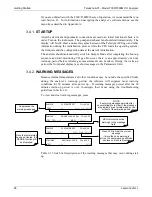
4.1.
SAMPLE MODE
This is the analyzer’s standard operating mode. In this mode the instrument is analyzing
the gas in the sample chamber, calculating CO concentration and reporting this
information to the user via the front panel display, the analog outputs and, if set up
properly, the RS-232/RS-485/Ethernet/USB ports.
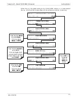
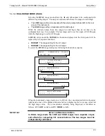
4.1.1.
TEST FUNCTIONS
A series of
TEST
functions is available for viewing at the front panel whenever the
analyzer is at the
SAMPLE
mode. These parameters provide information about the
present operating status of the instrument and are useful during troubleshooting (refer to
Section 11.1.2). They can also be recorded in one of the DAS channels (refer to Section
7.2) for data analysis. To view the test functions, press one of the <TST TST> buttons
repeatedly in either direction.
06864D DCN7562
Summary of Contents for T300
Page 2: ......
Page 182: ...06864D DCN7562 ...
Page 227: ...225 This page intentionally left blank 06864D DCN7562 ...
Page 228: ...06864D DCN7562 ...


