A C C E S S 2 4 1 - F X O / 2 4 1 / 2 1 1 / 2 1 1 N V O I P G A T E W A Y U S E R G U I D E
MN100129 Rev E
21
Installing your Access 211/Access 211N VoIP Gateway with a
Single PC
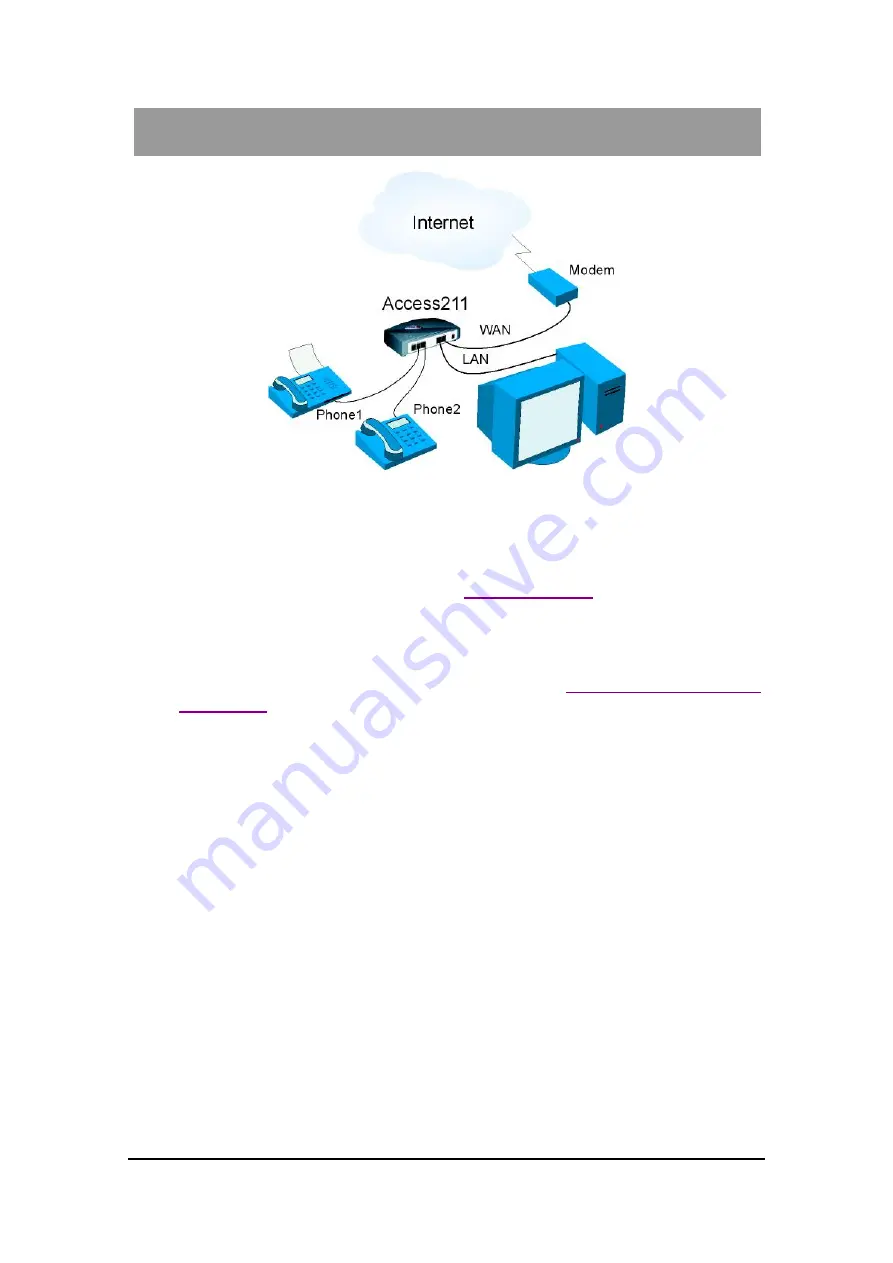
Figure 3: Access 211/Access 211N Single PC Installation
1.
Unpack the Gateway unit.
2.
Verify you have the components listed in the
list above.
3.
Place the Gateway on a desktop or other level surface, or mount it on a wall. Choose a
location that is near the devices to be connected and close to a wall socket.
If you want to mount the Access 211 on the wall, refer to
4.
Connect the WAN port on the Gateway’s rear panel to the Ethernet socket on your
broadband modem using an Ethernet 10/100BaseTX (RJ-45) cable.
5.
Connect the LAN port on the Gateway’s rear panel to the network socket on your PC using
an Ethernet 10/100BaseTX (RJ-45) cable.
6.
Use Phone cables to connect the telephones to the Phone1/PH1 and Phone2/PH2 on the rear
of the Gateway. (If your provider enables only one phone line, connect the phone to the
Phone1/PH1 port)
It is possible to connect up to five phones in parallel to each phone port. To do so, connect a
5-way splitter to the phone port. (If your provider enables only one phone line, use the
Phone1 port on the Gateway).
7.
Verify that all system components are properly installed. Secure all cable connectors in the
appropriate ports.
8.
Connect the power adapter to the Gateway’s power connector on the rear of the unit.
Connect the power adapter to a wall socket.
9.
Check that the Power LED on the Gateway’s front panel glows steadily.


