90
SPG8000A User Manual
General overlay settings
These
menu items appear at the top of the Overlay
submenu:
•
Text/Circle Blink Enable
:
Select this check box to enable the blinking
function of the text and circle overlays. When enabled, use the drop
-
down
list
to select a fast or slow blinking mode.
Select the
Fast
blink mode to set the overlay to blink at approximately
0.5 second intervals. Select the
Slow
blink mode to set the overlay to blink
at approximately 1.0 second intervals.
•
Border Enable
:
Select this check box to display a black border around the
text and circle overlays.
Note
:
Turn on the border to provide cleaner transitions between the overlay and the
test signal. This is especially useful for 4:2:2 format signals, which may have some
ringing when the border is turned off.
Logo overlay settings
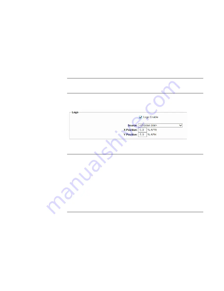
Use these settings to select a logo to overlay on the output test signal and to set the
display position of the logo. Figure
shows the Overlay Logo settings.
Figure 23: SDI Overlay Logo settings
Note
:
To display a logo, you need to create a logo file (.bmp) and use FTP or a
USB memory device to copy the file to the SDI7/Logo directory on the instrument.
The file must be installed in the Logo folder. Files installed in the wrong location
will be ignored by the instrument. (See
Transfer or install user files
Logo displays work best with the uncompressed BMP images (24 bits and 32 bits
true color). Logo displays do not work with RLE8 or RLE4 BMP compression.
BMP
files
are
not
scaled
for
each
raster
size.
For
example,
a
320×240
size
bitmap
will be
rendered
as 320×240 pixels regardless of the current raster area. The bitmap
would
occupy
about
25%
of
the
active
video
for
the SD-525
format,
but
less than 4%
of a 1920×1080 picture. Therefore, you might need to choose a bitmap size
appropriate for the target display resolution when using the logo
overlay.
These
settings are available for the Logo overlay:
•
Logo Enable
:
Select this check box to enable the Logo overlay and to
enable the Logo overlay control settings.
•
Source
:
Use the drop-
down list to select a logo file stored in the
SDI7/Logo directory.
The default logo is the “first”
file in the SDI7/Logo directory, as sorted by
the date of the logo file (oldest first). If the factory
-
provided logo files are
Summary of Contents for SPG8000A
Page 53: ...SPG8000A User Manual 39 Figure 7 Removing a Power Supply module...
Page 103: ...SPG8000A User Manual 89 Figure 22 SDI Overlay submenu...
Page 182: ...168 SPG8000A User Manual Figure 61 AES button menu diagram...
Page 190: ...176 SPG8000A User Manual Figure 73 EMBED button menu diagram...
Page 194: ...180 SPG8000A User Manual Figure 77 DOLBY E CONFIG submenu diagram part 2...
Page 197: ...SPG8000A User Manual 183 Figure 81 REF button menu diagram part 2...
Page 200: ...186 SPG8000A User Manual Figure 84 SDI button menu diagram part 2...
Page 211: ...SPG8000A User Manual 197 Figure 96 SDI ANC PAYLOAD submenu diagram part 2...
Page 213: ...SPG8000A User Manual 199 Figure 97 STATUS button menu diagram part 1...
Page 215: ...SPG8000A User Manual 201 Figure 99 SYSTEM button menu diagram part 1...
Page 216: ...202 SPG8000A User Manual Figure 100 SYSTEM button menu diagram part 2...
Page 225: ...SPG8000A User Manual 211 Figure 107 SNMP TRAPS submenu diagram part 2...
Page 240: ...226 SPG8000A User Manual Figure 123 PTP primary master menu diagram part 1...
Page 241: ...SPG8000A User Manual 227 Figure 124 PTP primary master menu diagram part 2...
Page 243: ...SPG8000A User Manual 229 Figure 126 PTP primary slave menu diagram part 2...


