SPG8000A User Manual
31
2.
Prepare the instrument for the firmware upgrade:
a.
Press
SYSTEM
on the front panel.
b.
Press the up (▲) or down (▼) arrow button to select
SYSTEM : FIRMWARE UPGRADE
.
c.
Press the left (◄) or right (►) arrow button to select
Network Upgrade
, and then press
ENTER
.
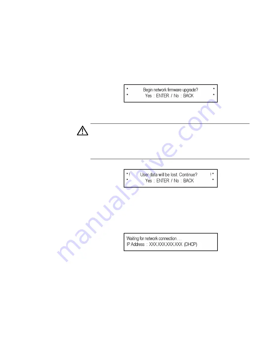
A confirmation message is displayed as shown.
A second, reminder,
confirmation about the loss of data
is
displayed
,
as shown
.
CAUTION
:
If you did not back up your user files as part of the upgrade
preparation process, we recommend you press the BACK button to cancel
the upgrade and then back up your user files before performing the
upgrade. The instructions for backing up user files is described in the
section
To transfer user files from an instrument to a USB drive
. You will
restore the user files at the end of the upgrade procedure.
d.
Press
ENTER
to continue
with the upgrade or press
BACK to cancel the upgrade.
When you press ENTER, a Waiting for network
c
onnection message is displayed, as shown, with the IP
address of the instrument. This indicates the instrument is
ready to be upgraded.
3.
Perform the firmware upgrade:
a.
On the PC, double
-
click the
transfer.exe
file to launch the
transfer program.
b.
Enter the IP address or DNS name of the instrument you
are upgrading, and then press
Enter
.
The firmware upgrade process begins. Messages
indicating the progress of the upgrade appear in the
transfer program window and on the instrument display.
Summary of Contents for SPG8000A
Page 53: ...SPG8000A User Manual 39 Figure 7 Removing a Power Supply module...
Page 103: ...SPG8000A User Manual 89 Figure 22 SDI Overlay submenu...
Page 182: ...168 SPG8000A User Manual Figure 61 AES button menu diagram...
Page 190: ...176 SPG8000A User Manual Figure 73 EMBED button menu diagram...
Page 194: ...180 SPG8000A User Manual Figure 77 DOLBY E CONFIG submenu diagram part 2...
Page 197: ...SPG8000A User Manual 183 Figure 81 REF button menu diagram part 2...
Page 200: ...186 SPG8000A User Manual Figure 84 SDI button menu diagram part 2...
Page 211: ...SPG8000A User Manual 197 Figure 96 SDI ANC PAYLOAD submenu diagram part 2...
Page 213: ...SPG8000A User Manual 199 Figure 97 STATUS button menu diagram part 1...
Page 215: ...SPG8000A User Manual 201 Figure 99 SYSTEM button menu diagram part 1...
Page 216: ...202 SPG8000A User Manual Figure 100 SYSTEM button menu diagram part 2...
Page 225: ...SPG8000A User Manual 211 Figure 107 SNMP TRAPS submenu diagram part 2...
Page 240: ...226 SPG8000A User Manual Figure 123 PTP primary master menu diagram part 1...
Page 241: ...SPG8000A User Manual 227 Figure 124 PTP primary master menu diagram part 2...
Page 243: ...SPG8000A User Manual 229 Figure 126 PTP primary slave menu diagram part 2...


