background image

Trigger Setup

Triggering on Buses

You can use your oscilloscope to trigger on CAN, I

2

C, SPI, RS-232, RS-422, RS-485, UART, LIN, FlexRay, I

2

S, Left Justi

fi

ed, Right

Justi

fi

ed, and TDM buses, if you have the appropriate DPO4AUTO, DPO4AUTOMAX, DPO4EMBD, DPO4COMP, or DPO4AUDIO

application module installed. The MSO4000 Series can trigger on parallel buses without an application module. The oscilloscope
can display both physical layer (as analog waveforms) and protocol level information (as digital and symbolic waveforms).

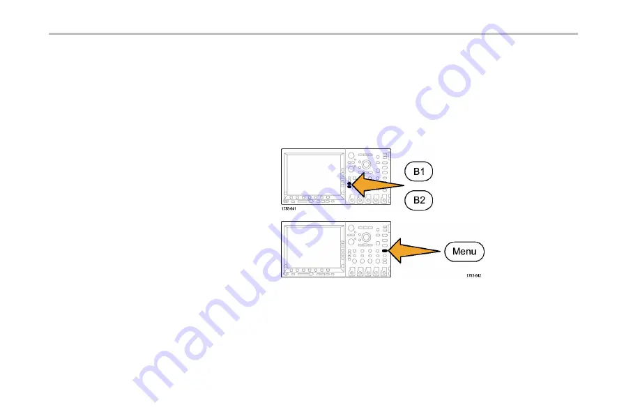
To set up the bus trigger:

1.

If you have not already de

fi

ned your bus using

the front-panel

B1

and

B2

buttons (and

B3

and

B4

on the MSO4000 Series), do so now. (See

page 100,

Setting Up a Serial or Parallel Bus

.)

2.

Push Trigger

Menu

.

146

MSO4000 and DPO4000 Series Oscilloscopes User Manual

Summary of Contents for DPO4032

Page 1: ...x MSO4000 and DPO4000 Series Digital Phosphor Oscilloscopes ZZZ User Manual P071212103 071 2121 03...

Page 2: ......

Page 3: ...MSO4000 and DPO4000 Series Digital Phosphor Oscilloscopes ZZZ User Manual xx www tektronix com 071 2121 03...

Page 4: ...trademarks of Tektronix Inc e Scope iView OpenChoice TekSecure and TekVPI are registered trademarks of Tektronix Inc MagniVu and Wave Inspector are trademarks of Tektronix Inc Tektronix is an authoriz...

Page 5: ...tomer shall be responsible for paying all shipping charges duties taxes and any other charges for products returned to any other locations This warranty shall not apply to any defect failure or damage...

Page 6: ......

Page 7: ...tions Used in This Manual xx Installation 1 Before Installation 1 Operating Considerations 8 Connecting Probes 13 Securing the Oscilloscope 16 Powering On the Oscilloscope 16 Powering Off the Oscillos...

Page 8: ...ectors 77 Side Panel Connector 78 Rear Panel Connectors 79 Acquire the Signal 81 Setting Up Analog Channels 81 Using the Default Setup 89 Using Autoset 90 Acquisition Concepts 91 How the Analog Acquis...

Page 9: ...a Waveform 161 Setting the Display Style and Persistence 162 Setting Waveform Intensity 168 Scaling and Positioning a Waveform 169 Setting Input Parameters 172 Positioning and Labeling Bus Signals 17...

Page 10: ...36 Saving a Screen Image 240 Saving and Recalling Waveform Data 242 Saving and Recalling Setups 247 Saving with One Button Push 250 Printing a Hard Copy 252 Erasing Oscilloscope Memory 263 Using Appli...

Page 11: ...Table of Contents Troubleshooting Circuits Using Parallel Buses 309 Troubleshooting an RS 232 Bus 313 Appendix Warranted Specifications 319 Index MSO4000 and DPO4000 Series Oscilloscopes User Manual v...

Page 12: ...Table of Contents vi MSO4000 and DPO4000 Series Oscilloscopes User Manual...

Page 13: ...disconnecting the current probe Ground the Product This product is grounded through the grounding conductor of the power cord To avoid electric shock the grounding conductor must be connected to earth...

Page 14: ...Do not touch exposed connections and components when power is present Do Not Operate in Wet Damp Conditions Do Not Operate in an Explosive Atmosphere Keep Product Surfaces Clean and Dry Provide Proper...

Page 15: ...injury hazard immediately accessible as you read the marking WARNING indicates an injury hazard not immediately accessible as you read the marking CAUTION indicates a hazard to property including the...

Page 16: ...006 EMC requirements for electrical equipment for measurement control and laboratory use 1 2 3 4 CISPR 11 2003 Radiated and conducted emissions Group 1 Class A IEC 61000 4 2 2001 Electrostatic dischar...

Page 17: ...o 2 7 GHz with 80 amplitude modulation at 1 kHz is not to exceed 8 major division s peak to peak Ambient fields may induce triggering when trigger threshold is offset less than 4 major divisions from...

Page 18: ...laboratory use U S Nationally Recognized Testing Laboratory Listing UL 61010 1 2004 2nd Edition Standard for electrical measuring and test equipment Canadian Certification CAN CSA C22 2 No 61010 1 200...

Page 19: ...ctive pollution occurs Occasionally a temporary conductivity that is caused by condensation must be expected This location is a typical office home environment Temporary condensation occurs only when...

Page 20: ...source of low voltage installation Measurement Category III For measurements performed in the building installation Measurement Category II For measurements performed on circuits directly connected t...

Page 21: ...terials are reused or recycled appropriately This symbol indicates that this product complies with the applicable European Union requirements according to Directives 2002 96 EC and 2006 66 EC on waste...

Page 22: ...l analog channels 10 M points record length on all channels 50 000 waveforms second display rate I2C SPI CAN LIN FlexRay RS 232 RS 422 RS 485 UART I2S Left Justified LJ Right Justified RJ TDM bus trig...

Page 23: ...SignalExpress Tektronix Edition productivity and analysis software Remote viewing and control with e Scope Remote control with VISA connectivity TekVPI Versatile Probe Interface supports active differ...

Page 24: ...Portuguese 071 2127 XX Simplified Chinese 071 2128 XX Traditional Chinese 071 2129 XX Korean 071 2130 XX Russian 071 2131 XX Specifications and Performance Verification The MSO4000 and DPO4000 Series...

Page 25: ...le Installation Instructions manual 071 2136 XX 11 languages Power measurement module DPO3PWR and DPO4PWR Power Measurement Module User Manual English 071 2631 XX French 077 0235 XX Italian 077 0236 X...

Page 26: ...face Conventions Used in This Manual The following icons are used throughout this manual Sequence Step Front panel power Connect power Network USB xx MSO4000 and DPO4000 Series Oscilloscopes User Manu...

Page 27: ...rd Accessories Accessory Description Tektronix part number English Option L0 071 2121 XX French Option L1 071 2122 XX Italian Option L2 071 2123 XX German Option L3 071 2124 XX Spanish Option L4 071 2...

Page 28: ...menting traceability to national metrology institute s and ISO9001 quality system registration For MSO4000 and DPO4000 Series Probes One 500 MHz 10X passive probe per channel P6139A Front Cover Hard p...

Page 29: ...nstallation Standard Accessories cont Accessory Description Tektronix part number For MSO4000 Series Logic probe One 16 channel logic probe P6516 MSO4000 and DPO4000 Series Oscilloscopes User Manual 3...

Page 30: ...BD DPO4AUTO The automotive serial triggering and analysis module enables triggering on packet level information on CAN and LIN serial buses as well as digital views of the signal bus views bus decodin...

Page 31: ...x if you need more details DPO4AUTOMAX DPO4COMP The computer triggering and analysis module enables triggering on RS 232 RS 422 RS 485 and UART serial buses search tools bus views bus decoding in hex...

Page 32: ...dapter TPA BNC TEK USB 488 Adapter GPIB to USB Adapter TEK USB 488 Getting Started with OpenChoice Solutions Manual with CD Describes ways to develop host computer software applications that work with...

Page 33: ...ications and performance verification procedure Available electronically on the Documentation Browser CD or for download from www tektronix com manuals 077 0247 XX Tektronix 4000 Series Oscilloscopes...

Page 34: ...to 132 V Power Consumption 250 W maximum Weight 5 kg 11 lbs standalone instrument Height including feet but not handle 229 mm 9 0 in Width from handle hub to handle hub 439 mm 17 3 in Depth from feet...

Page 35: ...RH Non operating Low 0 C to 40 C 5 to 90 RH DPO4000 Series Altitude Operating 3 000 m about 10 000 ft Nonoperating Altitude 12 192 m 40 000 ft Random Vibration Operating 0 31 GRMS 5 500 Hz 10 minutes...

Page 36: ...ctor and shield is 5 VRMS with peaks 20 V DF 6 25 Acquisition System Digital Inputs The maximum input voltage at the input for the logic probe is 15 V peak Aux In 1 M The maximum input voltage at the...

Page 37: ...VRMS at 20 MHz and above Output Voltage terminated into 1 M 40 VRMS or 40 V DC CAT I 2 500 Vpk impulse 30 VRMS or 30 V DC CAT I 250 Vpk impulse 15 VRMS or 15 V DC CAT I 250 Vpk impulse Temperature Ope...

Page 38: ...peak to peak Maximum nondestructive input signal to probe 15 V Input resistance 20 K Input capacitance 3 0 pF typical Temperature Operating 0 C to 50 C 32 F to 122 F Nonoperating 55 C to 75 C 67 F to...

Page 39: ...lint free cloth Use care to avoid scratching the clear glass display filter 2 Use a soft cloth dampened with water to clean the oscilloscope Use an aqueous solution of 75 isopropyl alcohol for more e...

Page 40: ...gh programmable support The remote control is useful in applications like ATE where you want the system to preset probe parameters 2 TPA BNC Adapter The TPA BNC Adapter allows you to use TEKPROBE II p...

Page 41: ...e signal and there is no other communication 4 Digital Probe Interface MSO4000 Series only The P6516 probe provides 16 channels of digital on or off state information For more information on the many...

Page 42: ...he power switch connect the oscilloscope to an electrically neutral reference point such as earth ground Do this by plugging the three pronged power cord into an outlet grounded to earth ground Ground...

Page 43: ...Static electricity that builds up on your body can damage static sensitive components Wearing a grounding strap safely sends static charges on your body to earth ground To connect the power cord and p...

Page 44: ...Installation 18 MSO4000 and DPO4000 Series Oscilloscopes User Manual...

Page 45: ...Installation Powering Off the Oscilloscope To power off the oscilloscope and remove the power cord MSO4000 and DPO4000 Series Oscilloscopes User Manual 19...

Page 46: ...nctional check to verify that your oscilloscope is operating correctly 1 Connect the oscilloscope power cable as described in Powering On the Oscilloscope See page 16 2 Power on the oscilloscope 20 MS...

Page 47: ...Installation 3 Connect the P6139A probe tip and reference lead to the PROBE COMP connectors on the oscilloscope 4 Push Default Setup MSO4000 and DPO4000 Series Oscilloscopes User Manual 21...

Page 48: ...e Vertical scale to 500 mV If the signal appears but is misshapen perform the procedures for compensating the probe See page 23 Compensating a Passive Voltage Probe If no signal appears rerun the proc...

Page 49: ...o the corresponding oscilloscope input channel To properly compensate your passive probe 1 Follow the steps for the functional check See page 20 Functional Check 2 Check the shape of the displayed wav...

Page 50: ...Installation 3 If necessary adjust your probe Repeat as needed 24 MSO4000 and DPO4000 Series Oscilloscopes User Manual...

Page 51: ...pplication modules not installed in your oscilloscope The trial period begins when you power on the oscilloscope for the first time After 30 days you must purchase the module if you want to continue u...

Page 52: ...o the two slots with windows in the upper right corner of the front panel Two additional slots are directly behind the two that you can see To use these slots install the module with the label facing...

Page 53: ...age of the oscilloscope user interface and to change the front panel button labels through the use of an overlay 1 Push Utility 2 Push Utility Page Utility Page 3 Turn multipurpose knob a and select C...

Page 54: ...sh Set Date Time TekSecure Erase Memory About 5 Turn multipurpose knob a and select the desired language Choose among English French German Italian Spanish Brazilian Portuguese Russian Japanese Korean...

Page 55: ...the plastic front panel overlay is removed If you choose a language other than English place the plastic overlay for the language that you desire over the front panel to display labels in that languag...

Page 56: ...Date and Time To set the internal clock with the current date and time 1 Push Utility 2 Push Utility Page Utility Page 3 Turn multipurpose knob a and select Config Config 30 MSO4000 and DPO4000 Series...

Page 57: ...Date Time TekSecure Erase Memory About 5 Push the side bezel buttons and turn both multipurpose knobs a and b to set the time and date values Set Date Time Display Date Time On Off Hour 4 Minute 1 Mon...

Page 58: ...Installation Year 2007 6 Push OK Enter Date Time OK Enter Date Time 32 MSO4000 and DPO4000 Series Oscilloscopes User Manual...

Page 59: ...r once a week if you use vertical settings of 5 mV division or less Failure to do so may result in the instrument not meeting warranted performance levels at those volts div settings To compensate the...

Page 60: ...ity Page Utility Page 4 Turn multipurpose knob a and select Calibration Calibration 5 Push Signal Path from the lower bezel menu Utility Page Calibration Signal Path Pass Factory Pass 34 MSO4000 and D...

Page 61: ...does not then recalibrate the instrument or have the instrument serviced by qualified service personnel 8 Service personnel use the factory calibration functions to calibrate the internal voltage refe...

Page 62: ...Web browser and go to www tektronix com software Proceed to the software finder Download the latest firmware for your oscilloscope on your PC Unzip the files and copy the firmware img file into the r...

Page 63: ...Installation 2 Power off your oscilloscope MSO4000 and DPO4000 Series Oscilloscopes User Manual 37...

Page 64: ...Installation 3 Insert the USB flash drive into the front panel USB port on your oscilloscope 38 MSO4000 and DPO4000 Series Oscilloscopes User Manual...

Page 65: ...not install the firmware rerun the procedure If the problem continues try a different model of USB flash drive Finally if needed contact qualified service personnel NOTE Do not power off the oscillosc...

Page 66: ...Installation 5 Power off the oscilloscope and remove the USB flash drive 40 MSO4000 and DPO4000 Series Oscilloscopes User Manual...

Page 67: ...Installation 6 Power on the oscilloscope 7 Push Utility MSO4000 and DPO4000 Series Oscilloscopes User Manual 41...

Page 68: ...onfig Config 10 Push About The oscilloscope displays the firmware version number Utility Page Config Language English Set Date Time TekSecure Erase Memory About 11 Confirm that the version number matc...

Page 69: ...to communicate with your oscilloscope from your computer through a software application Use e Scope to communicate with your oscilloscope through a Web browser Using VISA VISA lets you use your MS Wi...

Page 70: ...le To communicate between the oscilloscope and a GPIB system connect the oscilloscope to the TEK USB 488 GPIB to USB Adapter with a USB cable Then connect the adapter to your GPIB system with a GPIB c...

Page 71: ...he system sets itself up automatically for you if USB is enabled Utility Page I O USB Computer Ethernet Network Settings GPIB 1 Check USB on the lower bezel menu to be sure that USB is enabled If it i...

Page 72: ...hrough cable set DHCP to On If you are using a cross over cable set it to Off and set a hard coded TCPIP address Test Connection 8 If you are using GPIB push GPIB Enter the GPIB address on the side be...

Page 73: ...ars that speed connectivity with Microsoft Excel and Word There is also a standalone acquisition program called the OpenChoice Desktop The rear panel USB 2 0 device port is the correct USB port for co...

Page 74: ...access any Internet connected DPO4000 or MSO4000 Series oscilloscope from a browser on your workstation PC or laptop computer No matter where you are your oscilloscope is as close as the nearest brow...

Page 75: ...cope to your computer network with the appropriate Ethernet cable If you are connecting directly to your computer you need a Crossover Ethernet Cable If you are connecting to a network or a hub you ne...

Page 76: ...llation 4 Turn multipurpose knob a and select I O I O 5 Push Ethernet Network Settings Utility Page I O USB Computer Ethernet Network Settings GPIB 1 50 MSO4000 and DPO4000 Series Oscilloscopes User M...

Page 77: ...note the Ethernet address and instrument name If you are using Static addressing enter the Ethernet address you will be using DHCP BOOTP On Off Test Connection NOTE Depending on the type and speed of...

Page 78: ...o Your Oscilloscope You can connect a USB keyboard to a USB Host port on the rear or front panel of the oscilloscope The oscilloscope will detect the keyboard even if it is plugged in while the oscill...

Page 79: ...with the Instrument Front Panel Menus and Controls The front panel has buttons and controls for the functions that you use most often Use the menu buttons to access more specialized functions MSO4000...

Page 80: ...nu system 1 Push a front panel menu button to display the menu that you want to use You can use the B1 through B4 buttons on the MSO4000 Series oscilloscopes to support up to four different serial or...

Page 81: ...menu appears press the button again to select the desired choice 3 Push a side bezel button to choose a side bezel menu item If the menu item contains more than one choice push the side bezel button...

Page 82: ...equire you to set a numeric value to complete the setup Use the upper and lower multipurpose knobs a and b to adjust values 6 Push Fine to turn off or on the ability to make smaller adjustments Using...

Page 83: ...isition for user defined events criteria 3 Test Push to activate advanced or application specific testing features 4 Acquire Push to set the acquisition mode and adjust the record length 5 Autoset Pus...

Page 84: ...e 8 Save Recall Menu Push to save and recall setups waveforms and screen images to internal memory a CompactFlash card or a USB flash drive 9 Channel 1 2 3 or 4 Menu Push to set vertical parameters fo...

Page 85: ...supports I2S Left Justified LJ Right Justified RJ and TDM buses Also push the B1 or B2 button to display or remove the corresponding bus from the display On the MSO4000 Series you can use the B3 and...

Page 86: ...o select from a pop out list of choices Push the Fine button to toggle between coarse and fine adjustment Screen icons tell you when a or b are active 2 Cursors Push once to activate the two vertical...

Page 87: ...sible you can push this button to make either the vertical cursors or the horizontal cursors active 4 Fine Push to toggle between making coarse and fine adjustments with the vertical and horizontal po...

Page 88: ...Pan outer knob Turn to scroll the zoom window through the acquired waveform 9 Zoom inner knob Turn to control the zoom factor Turning it clockwise zooms in further Turning it counterclockwise zooms o...

Page 89: ...Push to jump to the next waveform mark 14 Horizontal Position Turn to adjust the trigger point location relative to the acquired waveforms Push Fine to make smaller adjustments 15 Horizontal Scale Tu...

Page 90: ...Push to automatically set the vertical horizontal and trigger controls for a usable stable display 19 Trigger Level Turn to adjust the trigger level 20 Set to 50 Push to set the trigger level to the...

Page 91: ...corresponding waveform from the display and access the vertical menu 24 Vertical Scale Turn to adjust the vertical scale factor of the corresponding waveform volts division 25 Print Push to print a sc...

Page 92: ...28 CompactFlash Drive Insert a CompactFlash card here 29 CompactFlash Eject Pops the CompactFlash card out of the CompactFlash drive 30 Save Push to perform an immediate save operation The save operat...

Page 93: ...Push to display or remove the digital channels from the display and to access the digital channel setup menu MSO4000 Series only 33 Menu Off Push to clear a displayed menu from the screen MSO4000 and...

Page 94: ...in the Display The items shown to the right may appear in the display Not all of these items are visible at any given time Some readouts move outside the graticule area when menus are turned off 68 M...

Page 95: ...cons are Run Acquisitions enabled Stop Acquisitions not enabled Roll In roll mode 40 ms div or slower PreVu In this state the oscilloscope is stopped or between triggers You can change the horizontal...

Page 96: ...e expansion point icon an orange triangle shows the point that the horizontal scale expands and compresses around 4 The waveform record view shows the trigger location relative to the waveform record...

Page 97: ...to Acquiring untriggered data PrTrig Acquiring pretrigger data Trig Waiting for trigger 6 The cursor readout shows time amplitude and delta values for each cursor For FFT measurements it shows frequen...

Page 98: ...ger readout shows the trigger source slope and level The trigger readouts for other trigger types show other parameters 9 The top line of the record length sampling rate readout shows the sampling rat...

Page 99: ...tween when the trigger occurs and when you actually capture the data Insert a negative time to capture more pretrigger information With Delay Mode off the bottom line shows the time location of the tr...

Page 100: ...the display To obtain a proper numerical measurement turn the vertical scale and position knobs to make all of the waveform appear in the display 13 The auxiliary waveform readouts show the vertical...

Page 101: ...et The icon colors correspond to the waveform colors 16 For digital channels MSO4000 Series only the baseline indicators point to the high and low levels The indicator colors follow the color code use...

Page 102: ...ital channels are grouped MSO4000 Series only 18 The bus display shows decoded packet level information for serial buses or for parallel buses MSO4000 Series only The bus indicator shows the bus numbe...

Page 103: ...3 Aux In Trigger level range is adjustable from 8 V to 8 V The maximum input voltage is 400V peak 250V RMS Input resistance is 1 M 1 in parallel with 13 pF 2 pF 4 PROBE COMP Square wave signal source...

Page 104: ...Get Acquainted with the Instrument Side Panel Connector 1 Ground strap connector This is a receptacle for a grounding strap 78 MSO4000 and DPO4000 Series Oscilloscopes User Manual...

Page 105: ...out HI is 2 5V open circuit 1 0 V into a 50 load to ground The logic level for Vout LO is 0 7 V into a load of 4 mA 0 25 V into a 50 load to ground 2 XGA Out Use the XGA Video port DB 15 female connec...

Page 106: ...your GPIB software applications on USB hardware Also use the USB port to connect a PictBridge compatible printer to the oscilloscope 5 Host Use the USB 2 0 Full speed host ports two on the rear panel...

Page 107: ...he oscilloscope to acquire the signal as you want it to Setting Up Analog Channels Use front panel buttons and knobs to set up your instrument to acquire signals using the analog channels 1 Connect th...

Page 108: ...ont panel buttons NOTE If you are using a probe that does not supply probe encoding set the attenuation probe factor on the oscilloscope vertical menu for the channel to match the probe 3 Push Default...

Page 109: ...Acquire the Signal 4 Push Autoset 5 Push the desired channel button Then adjust the vertical position and scale MSO4000 and DPO4000 Series Oscilloscopes User Manual 83...

Page 110: ...o see multiple cycles of your signal in the upper part and a single cycle in the lower part of the display See page 224 Using Wave Inspector to Manage Long Record Length Waveforms Labeling Channels an...

Page 111: ...tton for an input channel or a bus 2 Push a lower bezel button to create a label such as for channel 1 or B1 Label 3 Push Select Preset Label to view a list of labels Select Preset Label MSO4000 and D...

Page 112: ...sert it if necessary 5 Push Insert Preset Label to add the label Insert Preset Label If you are using a USB keyboard use the arrow keys to position the insertion point and edit the inserted label or t...

Page 113: ...to position the insertion point 7 Turn multipurpose knob a to scroll through the list of letters numbers and other characters to find the character in the name that you want to enter ABCDEFGHIJKLMNOP...

Page 114: ...the label as needed Enter Character Back Space Delete Clear 9 Continue scrolling and pushing Select until you have entered all the desired characters For another label push the side and lower bezel ar...

Page 115: ...t Setup To return the oscilloscope to its default settings 1 Push Default Setup 2 If you change your mind push Undo Default Setup to undo the last default setup Undo Default Setup MSO4000 and DPO4000...

Page 116: ...er near the midlevel and ten cycles for digital channels Autoset works with both the analog and digital channels 1 Connect the analog probe and then select the input channel See page 81 Setting Up Ana...

Page 117: ...f you use Autoset and the oscilloscope detects a video signal the oscilloscope automatically sets the trigger type to video and makes other adjustments to display a stable video signal Acquisition Con...

Page 118: ...rm record which is then stored in acquisition memory Input signal Sampled points Digital values Real Time Sampling Record points DPO4000 and MSO4000 Series oscilloscopes use real time sampling In real...

Page 119: ...urning the Horizontal Scale knob or changing the record length with the bezel buttons Record length The number of samples required to fill a waveform record Set this by pushing the Acquire button and...

Page 120: ...the record after the trigger point Use a negative time to acquire it before the trigger point Expansion point The point that the horizontal scale expands and contracts around It is shown by an orange...

Page 121: ...l This mode also only works with real time noninterpolated sampling Hi Res provides a higher resolution lower bandwidth waveform Envelope mode finds the highest and lowest record points over all acqui...

Page 122: ...Length and Delay Time Use this procedure to change the acquisition mode 1 Push Acquire 2 Push Mode Mode Sample Record Length 10k Delay On Off Set Horiz Position to 10 Waveform Display XY Display Off...

Page 123: ...that the oscilloscope would have discarded at lower sweep speeds Therefore these modes only work when the current sample rate is less than the maximum possible sample rate As soon as the oscilloscope...

Page 124: ...over 5 Push Record Length 6 Push the side bezel menu record length button 10k points Choose among 1000 10 k 100 k 1 M and 10 M points 7 Push the lower bezel Delay button to select On when you want to...

Page 125: ...he delay feature when you want to acquire waveform detail that is separated from the trigger event by a significant interval of time For example you can trigger on a sync pulse that occurs once every...

Page 126: ...n signal events or conditions that occur on I2C and SPI serial buses if the DPO4EMBD application module is installed CAN and LIN serial buses if the DPO4AUTO or DPO4AUTOMAX application module is insta...

Page 127: ...See page 25 Application Module Free Trial Using Buses in Two Steps To quickly use serial bus triggering 1 Push B1 or B2 and enter parameters of the bus on which to trigger You can separately use B1 an...

Page 128: ...ation without triggering on the bus signal Setting Up Bus Parameters NOTE For all serial bus sources use any combination of channels 1 through 4 and D15 through D0 To trigger on serial or parallel bus...

Page 129: ...t of bus types and select the desired bus Parallel MSO4000 Series only I2C SPI CAN RS 232 LIN FlexRay or Audio B1 Parallel Define Inputs Thresholds B1 Label Parallel Bus Display Event Table The actual...

Page 130: ...side bezel button to select the Clock Edge on which to clock data rising edge falling edge or both edges Clock Edge Turn multipurpose knob a to select the Number of Data Bits in the parallel bus Numb...

Page 131: ...pes of integrated circuits The preset values are 1 4 V for TTL 2 5 V for 5 0 V CMOS 1 65 V for 3 3 V CMOS 1 25 V for 2 5 V CMOS 1 3 V for ECL 3 7 V for PECL 0 V Alternately you can set the threshold t...

Page 132: ...lloscope treats the signal as a logic high and below which as a logic low 5 Push B1 Label to edit the label for the bus See page 84 Labeling Channels and Buses Bus Parallel Define Inputs Thresholds B1...

Page 133: ...to define how to display the parallel or serial bus Hex Push the desired side bezel menu choice to display the bus data in hexadecimal binary ASCII RS 232 only or Signed Decimal Audio only format Bina...

Page 134: ...he value of the bus at each clock edge For an unclocked parallel bus the table lists the value of the bus whenever any one of its bits changes For an RS 232 bus the table lists decoded bytes or packet...

Page 135: ...y one line for each packet when Packets are set to On I2C SPI CAN and LIN event tables display one line for each packet 9 Push B1 or B2 and turn multipurpose knob a to move the bus display up or down...

Page 136: ...I2C addresses in bus decode traces cursor readouts Event Table listings and trigger settings If you select Yes the oscilloscope displays 7 bit addresses as eight bits where the eighth bit LSB is the...

Page 137: ...ide bezel menu choices Bus SPI Define Inputs Thresholds Configure B1 Label SPI Bus Display Event Table You can set the Framing to SS Slave Select or to Idle Time You can assign the predefined SCLK SS...

Page 138: ...I bus SS Active High Active Low Active High means that a signal is considered active when the signal is greater than the threshold value MOSI Active High Active Low Active Low means that the signal is...

Page 139: ...order of the SPI bus Bit Order MS First Bit Order LS First To acquire data from a CAN bus you need to also set up these items 1 If you selected CAN push Define Inputs and the appropriate side bezel m...

Page 140: ...1 3 Turn multipurpose knob a to select the type of CAN signal CAN_H CAN_L Rx Tx or Differential Signal Type CAN_H 4 Turn multipurpose knob a to set the Sample Point from 5 to 95 of the position withi...

Page 141: ...the bit rate to a specific value To do so select Custom and then turn multipurpose knob b to set the bit rate from 10 000 to 1 000 000 To acquire data from a LIN bus you need to also set up these item...

Page 142: ...of the position within the bit period or the unit interval Sample Point 50 4 Select the Polarity to match the LIN bus being acquired Polarity Normal High 1 Polarity Inverted High 0 5 Push Configure an...

Page 143: ...ob b to set the bit rate from 800 bps to 100 000 bps Bit Rate a 19 2K bps 7 Push LIN Standard and turn multipurpose knob a to select the appropriate standard LIN Standard v1 x 8 Push Include Parity Bi...

Page 144: ...ces Bus RS 232 Define Inputs Thresholds Configure 9600 8 N B1 Label RS 232 Bus Display Event Table Use the side bezel menu to configure the bus Use Normal polarity for RS 232 signals and Inverted pola...

Page 145: ...polarity used by the bus as None Odd or Even Parity a None 5 Push Packets and select On or Off Packets On Off 6 Turn multipurpose knob a to select an end of packet character End of Packet 0A Linefeed...

Page 146: ...If you selected Audio push Define Input and the desired side bezel menu choices Bus Audio Define Inputs Thresholds Configure B1 Label RS 232 Bus Display Event Table 120 MSO4000 and DPO4000 Series Osci...

Page 147: ...eft Justified to trigger on an I2S stream where there is no bit clock delay and the data starts right on the edge of the word select clock Left Justified LJ 5 Select Right Justified to trigger on an I...

Page 148: ...st NOTE The oscilloscope displays the decode traces and event tables for all buses with the MSB on the left and LSB on the right For example an RS 232 signal after the start bit might be high high hig...

Page 149: ...indicates that the value represents a character outside the printable ASCII range Setting Up Digital Channels Use front panel buttons and knobs to set up your instrument to acquire signals using the d...

Page 150: ...Acquire the Signal 1 Connect the P6516 16 channel logic probe to the input signal source 124 MSO4000 and DPO4000 Series Oscilloscopes User Manual...

Page 151: ...eeded connect the appropriate grabber for each probe to the probe tip 4 Connect the each probe to the desired circuit test point 5 Push the D15 D0 front panel button to display the menu 6 Push the low...

Page 152: ...to move all the channels in the group instead of individual channels 8 Push the lower bezel Thresholds button You can assign a different threshold value to each channel 9 Push the lower bezel Edit Lab...

Page 153: ...cord Length Waveforms When setting up the logic probe the first set of eight leads pins 7 to 0 on the logic probe are marked GROUP 1 on the lead box The second set pins 15 to 8 is marked GROUP 2 The l...

Page 154: ...a maximum resolution of 60 6 ps for 10 000 points centered around the trigger NOTE MagniVu centers itself around the trigger point If you turn MagniVu on while using a large record length and you are...

Page 155: ...nk you need more timing resolution turn on MagniVu to increase the resolution MagniVu is always acquired If the oscilloscope is in a stopped state you can turn on MagniVu and still get the resolution...

Page 156: ...sample points to fill the pretrigger portion of the waveform record That is the part of the waveform that is displayed before or to the left of the triggering event on screen When a trigger event occ...

Page 157: ...cquire a waveform even if a trigger does not occur Auto mode uses a timer that starts when the acquisition is started and the pretrigger information is obtained If a trigger event is not detected befo...

Page 158: ...ger events Trigger holdoff can help stabilize triggering since the oscilloscope does not recognize new triggers during the holdoff time When the instrument recognizes a trigger event it disables the t...

Page 159: ...types DC Low Frequency Rejection High Frequency Rejection and Noise Rejection All other trigger types use DC coupling only Horizontal Position When Delay Mode is on use horizontal position to acquire...

Page 160: ...data can help you troubleshoot For example to find the cause of an unwanted glitch in your test circuit you can trigger on the glitch and make the pretrigger period large enough to capture data before...

Page 161: ...r point on the rising or the falling edge of a signal The level control determines where on that edge the trigger point occurs The oscilloscope provides a long horizontal bar or bars across the gratic...

Page 162: ...l Trigger Level knob to adjust the trigger level without going to a menu 2 Push the front panel Set to 50 button to quickly set the trigger level to the midpoint of the waveform 136 MSO4000 and DPO400...

Page 163: ...Trigger Setup Choosing a Trigger Type To select a trigger 1 Push Trigger Menu MSO4000 and DPO4000 Series Oscilloscopes User Manual 137...

Page 164: ...el menu NOTE The bus trigger in the MSO4000 Series works on parallel buses even without an application module Using the bus trigger on other buses requires use of the DPO4EMBD DPO4AUTO DPO4AUTOMAX or...

Page 165: ...Triggers Trigger Type Trigger Conditions Edge Trigger on a rising or falling edge as defined by the slope control Coupling choices are DC LF Reject HF Reject and Noise Reject Edge triggers are the si...

Page 166: ...ount of time and then looks for the B Event before triggering and displaying the waveform Events After the A Event occurs the trigger system looks for a specified number of B Events before triggering...

Page 167: ...ails to cross a second threshold before recrossing the first You can detect positive or negative or either runts or only those wider than less than greater than equal to or not equal to a specified wi...

Page 168: ...olarity of the clock edge Turn off clocked triggering and return to unclocked pattern triggering by selecting the clock channel and setting it to high low or don t care For unclocked triggering by def...

Page 169: ...ltiple channel Setup and Hold triggering and can monitor the state of an entire bus for setup and hold violations You can use up to 20 channels for a Setup and Hold trigger 4 analog and 16 digital wit...

Page 170: ...ositive or negative or either Video Trigger on specified fields or lines of a composite video signal Only composite signal formats are supported Trigger on NTSC PAL or SECAM Works with Macrovision sig...

Page 171: ...e CAN requires a DPO4AUTO or DPO4AUTOMAX module RS 232 RS 422 RS 485 and UART require a DPO4COMP module LIN requires either a DPO4AUTO or a DPO4AUTOMAX module FlexRay requires a DPO4AUTOMAX module Par...

Page 172: ...MSO4000 Series can trigger on parallel buses without an application module The oscilloscope can display both physical layer as analog waveforms and protocol level information as digital and symbolic w...

Page 173: ...ff 4 Turn multipurpose knob a to scroll through the trigger type side menu until you select Bus B1 I2C 5 Push Source Bus and turn multipurpose knob a to scroll through the source bus side menu until y...

Page 174: ...trigger you can trigger on Start Repeated Start Stop Missing Ack Address Data or Address Data If you are using the SPI bus trigger you can trigger on SS Active MOSI MISO or MOSI MISO If you are using...

Page 175: ...ing up an I2C trigger and have made a Trigger On selection of Address or Address Data push the lower bezel Address button to access the I2C Address side bezel menu Push the side bezel Addressing Mode...

Page 176: ...and enter the number of bytes with multipurpose knob a Push the side bezel Addressing Mode button and select 7 bit or 10 bit Push the side bezel Data button Enter the data parameters of interest with...

Page 177: ...OSI or MISO button and enter the data parameters of interest with multipurpose knobs a and b Then push the Number of Bytes button and enter the number of bytes with multipurpose knob a If you select M...

Page 178: ...lower bezel Identifier button and select a Format Then push the Identifier side bezel button and enter a binary or hex value with multipurpose knobs a and b Push the lower bezel menu Direction button...

Page 179: ...have made a Trigger On selection of Identifier Data or Identifier Data push the lower bezel Identifier or Data buttons and enter the parameters of interest on the resulting side bezel menu If you hav...

Page 180: ...rpose knob a Specific byte matching non rolling window matching for a specific position in the packet for I2C SPI CAN and FlexRay You can trigger on a specific byte for I2C SPI CAN and FlexRay in seve...

Page 181: ...e No rolling window is used RS 232 Bus Trigger Data Matching You can trigger on a specific data value for RS 232 bytes If you defined an end of packet character to use for RS 232 bus decoding you can...

Page 182: ...ey trigger parameters check the Trigger readout at the bottom of the display The readouts differ for edge and the advanced triggers 1 Trigger source channel 1 2 Trigger slope rising 3 Trigger level 0...

Page 183: ...nd B triggers can and typically do have separate sources Use the Edge trigger menu to set up the A trigger first Then to use the B trigger 1 Push Trigger Menu 2 Push Type 3 Turn multipurpose knob a to...

Page 184: ...8 ns B Events 1 Set to Minimum 5 Set the other Sequence Trigger parameters in the related side and lower bezel menus B Trigger After Delay Time The A trigger arms the instrument Posttrigger acquisitio...

Page 185: ...position are independent functions When you establish a trigger condition using either the A trigger alone or the A and B triggers together you can also use the horizontal position control to delay t...

Page 186: ...uisition with Run Stop or Single Push Run Stop to start acquisitions The oscilloscope acquires repeatedly until you push the button again to stop the acquisition Push Single to take a single acquisiti...

Page 187: ...the acquired waveform Adding and Removing a Waveform 1 To add or remove a waveform from the display push the corresponding front panel channel button or the D15 D0 button You can use the channel as a...

Page 188: ...Style and Persistence 1 To set the display style push Acquire 2 Push Waveform Display Mode Sample Record Length 10k Delay On Off Set Horiz Position to 10 Waveform Display XY Display On 162 MSO4000 and...

Page 189: ...Set to Auto to have the oscilloscope automatically determine a persistence time for you Set to Auto 6 Push Clear Persistence to reset the persistence information Clear Per sistence 7 To display the a...

Page 190: ...he acquisition display settings Use infinite persistence for displaying unique signal anomalies such as glitches The XY Display mode graphs the data in fixed pairs of waveforms against one another You...

Page 191: ...n multipurpose knob a and select Display Display 4 Push Graticule from the lower bezel menu Utility Page Display Backlight Intensity High Graticule Full Screen Annotation MSO4000 and DPO4000 Series Os...

Page 192: ...er data Use the Frame graticule with automatic readouts and other screen text when display features are not needed Quick Tips You can display IRE and mV graticules To do this set the trigger type to v...

Page 193: ...tility 2 Push Utility Page Utility Page 3 Turn multipurpose knob a and select Display Display 4 Push Backlight Intensity Utility Page Display Backlight Intensity High Graticule Full Screen Annotation...

Page 194: ...intensity level from the resulting side bezel menu Choices are High Medium and Low Low Setting Waveform Intensity 1 Push the front panel Intensity button This will bring up the intensity readout on th...

Page 195: ...nsity readout from the display Scaling and Positioning a Waveform Use the horizontal controls to adjust the time base adjust the trigger point and to examine waveform details more closely You can also...

Page 196: ...cal controls to select waveforms adjust the waveform vertical position and scale and set input parameters Push a channel menu button 1 2 3 or 4 button as many times as needed and the associated menu i...

Page 197: ...es and repositions the relevant waveforms in response to the new control settings It simulates what you will see when you next push the RUN button The oscilloscope uses the new settings for the next a...

Page 198: ...l menu only affects the selected waveform Pushing a channel button will also select or cancel that waveform selection 2 Push Coupling repeatedly to select the coupling to use Use DC coupling to pass b...

Page 199: ...invert the signal Select Off for normal operation and On to invert the polarity of the signal in the preamplifier 5 Push Bandwidth and select the desired bandwidth from the resulting side bezel menu...

Page 200: ...e 84 Labeling Channels and Buses 7 Push More to access additional side bezel menus 8 Select Fine Scale to enable multipurpose knob a to make fine vertical scale adjustments Fine Scale Offset Position...

Page 201: ...purpose knob a to make vertical offset adjustments On the side bezel menu choose Set to 0 V to set the vertical offset to 0 V For more information on offset see Quick Tips See page 178 Quick Tips MSO4...

Page 202: ...set Attenuation to match the probe For probes that do not have a Tek interface when Probe Type is set to Current use multipurpose knob a to set the Amps Volts ratio Attenuation to match the probe If...

Page 203: ...recommended values based on the nominal propagation delay of each probe The oscilloscope automatically loads the nominal propagation delay values of TekVPI and TekProbe II requires use of a TPA BNC ad...

Page 204: ...ine indicators indicate the zero Volts or Amps level for each waveform If you adjust the channel s Vertical Scale the waveform expands or contracts around the waveform s baseline indicator When you us...

Page 205: ...he appropriate front panel bus button and turn multipurpose knob a to adjust the vertical position of the selected bus See page 100 Setting Up a Serial or Parallel Bus 1 Push the appropriate front pan...

Page 206: ...ltipurpose knob a to adjust the vertical position of the selected bus Labeling bus signals To label a bus do the following steps 1 Push the appropriate front panel bus button 180 MSO4000 and DPO4000 S...

Page 207: ...ling Channels and Buses Bus B1 Parallel Define Inputs Thresholds B1 Label Parallel Bus Display Event Table Positioning Scaling and Grouping Digital Channels 1 Push the front panel D15 D0 button MSO400...

Page 208: ...l D15 D0 menu item D15 D0 On Off Thresholds Edit Labels MagniVu On Off Height S M L 3 Push the side bezel Select button Select a D0 b 1 04 div Display On Off Turn on D7 D0 Turn on D15 D8 182 MSO4000 a...

Page 209: ...ose knob a to select the channel to move 5 Turn multipurpose knob b to move the selected channel NOTE The display of the channel or group only moves after you stop rotating the knob MSO4000 and DPO400...

Page 210: ...o display the waveforms You can display up to 10 L waveforms at one time 7 You can label individual digital channels for easier identification See page 84 Labeling Channels and Buses 8 To group some o...

Page 211: ...the transition edge is displayed in gray When multiple transitions occur during the time represented by one pixel column the transition edge is displayed in white When the display shows a white edge...

Page 212: ...the Screen You can add your own text to the screen by doing the following 1 Push Utility 2 Push Utility Page Utility Page 3 Turn multipurpose knob a and select Display Display 186 MSO4000 and DPO4000...

Page 213: ...tipurpose knobs a and b 6 Push Edit Annotation from the side bezel menu 7 Turn multipurpose knob a to scroll through the list of letters numbers and other characters to select each desired character A...

Page 214: ...gerable events whether the oscilloscope triggered on them or not and displays the number of times per second that they occur To display this readout do the following 1 Push Utility 2 Push Utility Page...

Page 215: ...tility Page Display Backlight Intensity High Graticule Full Screen Annotation Trigger Frequency Readout 5 Push On from the side bezel menu The trigger frequency now appears in the Trigger readout towa...

Page 216: ...lyze the results Select from features such as cursors automatic measurements statistics math and FFT Taking Automatic Measurements To take an automatic measurement 1 Push Measure 2 Push Add Measuremen...

Page 217: ...and push OK Remove Measurement on the side bezel menu Quick Tips To remove all measurements select Remove All Measurements A symbol appears instead of the expected numerical measurement if a vertical...

Page 218: ...between the mid reference default 50 amplitude point of two different waveforms See also Phase Rise Time The time required for the leading edge of the first pulse in the waveform or gated region to r...

Page 219: ...ent is made on the first pulse in the waveform or gated region Negative Pulse Width The distance time between the mid reference default 50 amplitude points of a negative pulse The measurement is made...

Page 220: ...er the entire waveform or gated region and is expressed as Positive Overshoot Maximum High Amplitude x 100 Negative Overshoot This is measured over the entire waveform or gated region and is expressed...

Page 221: ...thod uses the most common value found above the midpoint This value is measured over the entire waveform or gated region Low This value is used as 0 whenever high reference mid reference or low refere...

Page 222: ...ic mean over the entire waveform or gated region Cycle Mean The arithmetic mean over the first cycle in the waveform or the first cycle in the gated region RMS The true Root Mean Square voltage over t...

Page 223: ...Miscellaneous Measurements Measurement Description Rising Edge Count The number of positive transitions from the low reference value to the high reference value in the waveform or gated region Fallin...

Page 224: ...asurement is a voltage over time measurement It returns the area over the entire waveform or gated region in volt seconds Area measured above ground is positive area measured below ground is negative...

Page 225: ...nt reference levels or taking a snapshot Gating Gating confines the measurement to a certain portion of a waveform To use 1 Push Measure 2 Push More as many times as needed to select Gating from the r...

Page 226: ...the gates from the side bezel menu options Gating Off Full Record Screen Between Cursors Statistics Statistics characterize the stability of measurements To adjust statistics 200 MSO4000 and DPO4000...

Page 227: ...Push More as many times as needed to select Statistics from the resulting pop up menu Add Mea surement Remove Measure ment Indicators More Bring Cursors On Screen Configure Cursors MSO4000 and DPO400...

Page 228: ...menu options These include whether to turn statistics on or off and how many samples to use for mean and standard deviation calculations Reset Statistics Snapshot To see all the single sourced measur...

Page 229: ...up menu Add Mea surement Remove Measure ment Indicators More Bring Cursors On Screen Configure Cursors 3 Turn multipurpose knob a to select the Measurement Type of Snapshot 4 Push OK Snapshot All Mea...

Page 230: ...2 2 s 103 7 s 936 5 s 1 452 s 33 23 7 143 9 200 V 10 40 V 16 80 V 5 396 V 7 769 V 21 58mVs Freq Width Fall Duty Over Low Min Pk Pk CycleMean CycleRMS CycleArea 3 203kHz 208 5 s 1 144 s 66 77 7 143 7 6...

Page 231: ...ple they are used in calculating rise and fall times 1 Push Measure 2 Push More as many times as needed to select Reference Levels from the resulting pop up menu Add Mea surement Remove Measure ment I...

Page 232: ...Set Levels in Units Use High and Low reference to calculate rise and fall times High Ref a 90 0 Use Mid reference primarily for measurements between edges such as pulse widths Mid Ref 50 0 50 0 Low R...

Page 233: ...al channels 1 Push Cursors This changes the cursor state The three states are No cursors appear on the screen Two vertical waveform cursors appear They are attached to the selected analog waveform or...

Page 234: ...move the other cursor If you change the selected waveform by pushing the front panel 1 2 3 4 M R or D15 D0 button both cursors jump to the new selected waveform 3 Push Select This turns the cursor lin...

Page 235: ...hing Fine also changes the sensitivity of other knobs as well 5 Push Cursors again This will put the cursors into screen mode Two horizontal bars and two vertical bars span the graticule 6 Turn multip...

Page 236: ...u turn the multipurpose knobs the vertical cursors will move Push Select again to make the horizontal cursors active again 8 View the cursor and the cursor readout You can take timing measurements wit...

Page 237: ...the upper right corner of the graticule If Zoom is on the readout appears in the upper right corner of the zoom window When a bus is selected the readout shows the decoded bus data in the format you h...

Page 238: ...rolled by multipurpose knob a b Readout Indicates that the value is controlled by multipurpose knob b The horizontal cursor lines on the display measure the vertical parameters typically voltage The v...

Page 239: ...loscope will display vertical bar waveform cursors in the upper graticule YT Using Math Waveforms Create math waveforms to support the analysis of your channel and reference waveforms By combining and...

Page 240: ...Wfm Math Dual Wfm Math FFT Advanced Math M Label 3 On the side bezel menu set the sources to either channel 1 2 3 4 or reference waveforms R1 2 3 or 4 Choose the x or operators 214 MSO4000 and DPO4000...

Page 241: ...ame way as on channel waveforms Math waveforms derive their horizontal scale and position from the sources in their math expressions Adjusting these controls for the source waveforms also adjusts the...

Page 242: ...h of the frequency domain of a signal as opposed to the oscilloscope s standard time domain graph You can match these frequencies with known system frequencies such as system clocks oscillators or pow...

Page 243: ...cale button repeatedly to select either Linear RMS or dBV RMS Vertical Units Linear RMS 5 Push the side bezel Window button repeatedly to select the desired window Window choices are Rectangular Hammi...

Page 244: ...ency resolution If desired use the zoom feature along with the horizontal Position and Scale controls to magnify and position the FFT waveform Use the default dBV RMS scale to see a detailed view of m...

Page 245: ...use this window for equal amplitude sine waves with frequencies that are very close and for broadband random noise with a relatively slow varying spectrum Hamming This is a very good window for resol...

Page 246: ...minantly single frequency waveforms to look for higher order harmonics Using Advanced Math The advanced math feature lets you create a custom math waveform expression that can incorporate active and r...

Page 247: ...n done push the side bezel menu OK Accept button For example to use Edit Expression to take the integral of a square wave 1 Push the lower bezel Clear button 2 Turn multipurpose knob a to select Intg...

Page 248: ...e waveforms NOTE 10 M reference waveforms are volatile and not saved when the oscilloscope power is turned off To keep these waveforms save them to external storage 1 Push Ref R This brings up the low...

Page 249: ...o remove a reference waveform from the display push the front panel R button to access the lower bezel menu Then push the associated button from the lower bezel menu to turn it off Scaling and Positio...

Page 250: ...Inspector to Manage Long Record Length Waveforms The Wave Inspector controls zoom pan play pause marks search help you to efficiently work with long record length waveforms To magnify a waveform hori...

Page 251: ...knob on the Pan Zoom control clockwise to zoom in on a selected portion of the waveform Rotate the knob counterclockwise to zoom back out 2 Alternatively enable or disable the zoom mode by pushing th...

Page 252: ...upper portion of the display will show the position and size of the zoomed portion in the waveform within the context of the overall record Panning a Waveform While the zoom feature is on you can use...

Page 253: ...nob clockwise to pan forward Turn it counterclockwise to pan backwards The further you turn the knob the faster the zoom window pans Playing and Pausing a Waveform Use the play pause feature to automa...

Page 254: ...the direction that you are turning the pan knob 4 During play up to a point the more you turn the ring the faster the waveform accelerates If you rotate the ring as far as it can go the play speed do...

Page 255: ...ly mark each item of interest You can use arrow keys to jump from mark to mark area of interest to area of interest You can automatically search and mark many of the same parameters that you can trigg...

Page 256: ...row button to jump to an existing mark 2 Push Set Clear If no search mark is at the screen center the oscilloscope will add one 3 Investigate your waveform by moving from search mark to search mark Us...

Page 257: ...on both manually and automatically created marks To automatically set and clear delete search marks 1 Push Search 2 Select the search type desired from the lower bezel menu Search Off Search Type Edg...

Page 258: ...s are needed Quick Tips You can copy trigger settings to search for other locations in your acquired waveform that meet the trigger conditions You can also copy search settings to your trigger Custom...

Page 259: ...first again Search for all runt pulses or only those with a duration or a user specified time Logic Search for a logic pattern AND OR NAND or NOR across multiple waveforms with each input set to eithe...

Page 260: ...of Frame or Missing Ack Bit Stuffing Error RS 232 RS 422 RS 485 UART Search for Tx Start Bit Rx Start Bit Tx End of Packet Rx End of Packet Tx Data Rx Data Tx Parity Error Rx Parity Error LIN Search...

Page 261: ...on Analysis None 3 Use the side bezel buttons to select the desired analysis function Choose among power quality switching loss harmonics ripple modulation and safe operating area and deskew MSO4000 a...

Page 262: ...card E is the USB flash drive plugged into the USB port on the front of the oscilloscope F and G are the USB flash drives plugged into the USB ports on the rear of the oscilloscope Use multipurpose k...

Page 263: ...will have the same value for XXXX but the YYY values will be set to the different channels that were turned on when the Save All Waveforms was performed For example the first time you save a file that...

Page 264: ...call Waveform Recall Setup Assign Save to Setup File Utilities 3 For waveform or setup files enter the file manager by pushing the side bezel menu To File item To File 4 Turn multipurpose knob a to sc...

Page 265: ...ame Edit the file name the same way you edit labels for channels See page 84 Labeling Channels and Buses 7 Push the Menu Off button to cancel the save operation or push a side bezel menu OK Save item...

Page 266: ...To save a screen image 1 Push Save Recall Menu Do not yet push the Save button 2 Push Save Screen Image from the lower bezel menu Save Screen Image Save Waveform Save Setup Recall Waveform Recall Setu...

Page 267: ...to turn the Ink Saver mode on or off When on this mode provides a white background Ink Saver On Off 6 Push Edit File Name to create a custom name for the screen image file Skip this step to use a def...

Page 268: ...reen To save the current waveform data or to recall previously stored waveform data 1 Push Save Recall Menu 2 Push Save Waveform or Recall Waveform from the lower bezel menu Save Screen Image Save Wav...

Page 269: ...l it from Save the information externally to a file on a CompactFlash card or USB flash drive Alternatively save the information internally to one of the two reference memory files on 2 channel model...

Page 270: ...hese side bezel menu items for saving data to a mass storage file Side bezel menu button Description Internal File Format ISF Sets the oscilloscope to save waveform data from analog channels and math...

Page 271: ...want to save push the Save Waveform screen button and then select one of the reference waveform locations Four channel models have four reference locations Two channel models have two reference locat...

Page 272: ...y To remove a reference waveform from the display 1 Push Ref R 2 Push the R1 R2 R3 or R4 lower bezel button to remove the reference waveform from the display R1 On R2 Off R3 Off R4 Off The reference w...

Page 273: ...nt information It does not include communications information such as GPIB addresses To save the setup information 1 Push Save Recall Menu 2 Push Save Setup or Recall Setup from the lower bezel menu S...

Page 274: ...setup memories in the oscilloscope push the appropriate side bezel button To save setup information to a CompactFlash or USB file push the To File button To Setup 1 To Setup 2 more 4 If you are saving...

Page 275: ...a side bezel menu Save to Selected File item to complete the operation 5 Save the file Save to Selected File Quick Tips Recalling the Default Setup Push the front panel Default Setup button to initia...

Page 276: ...to save waveform data to a USB drive then each push of the Save button will save current waveform data to the defined USB drive 1 To define the Save button behavior push Save Recall Menu 2 Push Assign...

Page 277: ...form Setup 4 From now on when you push Save the oscilloscope will perform the action that you just specified rather than requiring you to navigate through the menus each time MSO4000 and DPO4000 Serie...

Page 278: ...Bridge printer to a USB port on the rear or front panel of the oscilloscope Alternatively connect a PictBridge printer to the USB device port on the rear panel or hook up a networked printer through t...

Page 279: ...n multipurpose knob a to scroll through the list of available printers Push Select to choose the desired printer To add a non PictBridge USB printer to the list plug the printer into a USB host port T...

Page 280: ...Save and Recall Information 5 Select the image orientation portrait or landscape Landscape Portrait 254 MSO4000 and DPO4000 Series Oscilloscopes User Manual...

Page 281: ...ill print out a copy with a clear white background Ink Saver on Ink Saver off Printing to a PictBridge Printer To set up the oscilloscope to print to a PictBridge printer 1 Push Utility 2 Push Utility...

Page 282: ...rmation 3 Turn multipurpose knob a and select I O I O 4 Push USB Utility Page I O USB Printer Ethernet Network Settings GPIB 1 USB Device Port Connect to Computer 256 MSO4000 and DPO4000 Series Oscill...

Page 283: ...ridge Printer Connect to PictBridge Printer Disabled Off bus Printing Over Ethernet To set up the oscilloscope to print over Ethernet 1 Connect an Ethernet cable to the rear panel Ethernet port MSO400...

Page 284: ...ush Utility Page Utility Page 4 Turn multipurpose knob a and select Print Setup Print Setup 5 Push Select Printer Utility Page Print Setup Select Printer Orientation Landscape Ink Saver Off 258 MSO400...

Page 285: ...and other characters to find the first character in the printer name that you want to enter If you are using a USB keyboard use the arrow keys to position the insertion point and type in the printer n...

Page 286: ...eeded Enter Character Back Space Delete Clear 9 Continue scrolling and pushing Select until you have entered all the desired characters 10 Push the down arrow key to move the character cursor down a r...

Page 287: ...to move the character cursor down a row to the Server IP Address field OK Accept 13 Turn multipurpose knob a and push Select or Enter Character as often as needed to enter the name 14 When done push O...

Page 288: ...Utility Utility Page Print Setup Select Printer menu item Printing with One Button Push Once you have connected a printer to your oscilloscope and set up print parameters you can print current screen...

Page 289: ...ecure function before you return the oscilloscope to general use The TekSecure function Replaces all waveforms in all reference memories with null values Replaces the current front panel setup and all...

Page 290: ...TekSecure Erase Memory Utility Page Config Language English Set Date Time TekSecure Erase Memory About 5 Push OK Erase Setup and Ref Memory from the side bezel menu OK Erase Setup Ref Memory To cance...

Page 291: ...Save and Recall Information 6 Power off the oscilloscope and then power it back on to complete the process MSO4000 and DPO4000 Series Oscilloscopes User Manual 265...

Page 292: ...r serial bus These include digital views of the signal bus views packet decoding search tools and event tables with timestamp information The DPO4AUTO Automotive Serial Triggering and Analysis Module...

Page 293: ...ideo signals with 3 to 4 000 lines The DPO4AUDIO Audio Serial Triggering and Analysis Module adds triggering on I2S Left Justified LJ Right Justified RJ and TDM buses The DPO4PWR Power Analysis Module...

Page 294: ...Using Application Modules 268 MSO4000 and DPO4000 Series Oscilloscopes User Manual...

Page 295: ...ing tasks Taking Simple Measurements If you need to see a signal in a circuit but you do not know the signal amplitude or frequency connect the probe from channel 1 of the oscilloscope to the signal T...

Page 296: ...lay of the waveform When you are using more than one channel the autoset function sets the vertical controls for each channel and uses the lowest numbered active channel to set the horizontal and trig...

Page 297: ...ors 3 Turn multipurpose knob a to select the Frequency measurement If needed press Source from the side menu and turn multipurpose knob b to select the channel from which you want to measure Push OK A...

Page 298: ...Application Examples 4 Push Menu Off 5 Observe that the measurements appear on the screen and update as the signal changes 272 MSO4000 and DPO4000 Series Oscilloscopes User Manual...

Page 299: ...r You have an audio generator that can inject a test signal at the amplifier input Connect two oscilloscope channels to the amplifier input and output as shown Measure both signal levels and use these...

Page 300: ...es 1 Push channel 1 and channel 2 to activate both channels 2 Push Autoset To select measurements for the two channels 1 Push Measure to see the measurement menu 274 MSO4000 and DPO4000 Series Oscillo...

Page 301: ...rn multipurpose knob a to select the Amplitude measurement from the side menu If needed press Source and turn multipurpose knob b to select channel 1 Push OK Add Measurement from the side menu Repeat...

Page 302: ...27 Gain dB 20 x log 24 27 27 7 dB Customizing Your Measurements In this example you want to verify that the incoming signal to digital equipment meets its specifications Specifically the transition t...

Page 303: ...tors More Bring Cursors On Screen Configure Cursors 3 Turn multipurpose knob a to select the Rise Time measurement If needed press Source from the side menu and turn multipurpose knob b to select the...

Page 304: ...urpose knob Low Ref a 800 mV Rise time is typically measured between the 10 and 90 amplitude levels of a signal These are the default reference levels that the oscilloscope uses for rise time measurem...

Page 305: ...snapshot of the digital signal do this step 1 Push Single to capture a single acquisition This assumes that the oscilloscope will trigger with the current settings Now you want to measure the width o...

Page 306: ...rement If needed press Source from the side menu and turn multipurpose knob b to select the channel from which you want to measure Push OK Add Measurement from the side menu 5 Push More repeatedly unt...

Page 307: ...Examples 7 Place one cursor to the left and one cursor to the right of the second pulse 8 View the resulting width measurement 160 ms for the second pulse MSO4000 and DPO4000 Series Oscilloscopes User...

Page 308: ...ou need to know more about it You suspect that the signal contains much more detail than you can currently see in the display Looking at a Noisy Signal The signal appears noisy You suspect that noise...

Page 309: ...amples 1 Push Acquire 2 Push Mode on the lower bezel menu Mode Sample Record Length 10k Delay On Off Set Horiz Position to 10 Waveform Display XY Display Off MSO4000 and DPO4000 Series Oscilloscopes U...

Page 310: ...s 3 Push Peak Detect on the side bezel menu Sample Peak Detect Hi Res Envelope Average 4 Push Intensity and turn multipurpose knob a to see the noise more easily 284 MSO4000 and DPO4000 Series Oscillo...

Page 311: ...time base is set to a slow setting Peak detect and the other acquisition modes are explained earlier in this manual See page 91 Acquisition Concepts Separating the Signal from Noise Now you want to an...

Page 312: ...sh Acquire 2 Push Mode Mode Sample Record Length 10K Delay On Off Set Horiz Position to 10 Waveform Display XY Display Off 3 Push Average on the side bezel menu Average 286 MSO4000 and DPO4000 Series...

Page 313: ...e to the right a ring shows on the rising and falling edges of the signal when the noise is removed Taking Cursor Measurements You can use the cursors to take quick measurements on a waveform To measu...

Page 314: ...annel 1 to select the channel 1 signal 2 Push Measure 3 Push Configure Cursors Add Mea surement Remove Measure ment Indicators More Bring Cursors On Screen Configure Cursors 288 MSO4000 and DPO4000 Se...

Page 315: ...ected Turn multipurpose knob a to select Hz 1 s as the unit of measurement 5 Push Cursors repeatedly until the two vertical bar cursors appear on the selected waveform 6 Place one cursor on the first...

Page 316: ...the cursors are linked push Select to unlink them 8 Place the other cursor on the next peak of the ring using multipurpose knob b 9 The cursor readout shows the measured ring frequency is 227 kHz 290...

Page 317: ...his example you are testing the video circuit in a piece of medical equipment and need to display the video output signal The video output is an NTSC standard signal Use the video signal to obtain a s...

Page 318: ...e menu until you select Video Video 4 Push Video Standard and turn multipurpose knob a to scroll through the standards until you select 525 NTSC Type Video Video Standard 525 NTSC Source 1 Trigger On...

Page 319: ...dd Fields Odd Fields If the signal had been noninterlaced you could choose to trigger on All Fields 7 Turn the Horizontal Scale knob to see a complete field across the screen MSO4000 and DPO4000 Serie...

Page 320: ...Application Examples 8 View results Triggering on Lines Triggering on Lines To look at the video lines in the field 1 Push Trigger Menu 294 MSO4000 and DPO4000 Series Oscilloscopes User Manual...

Page 321: ...tipurpose knob a to scroll through the trigger type side menu until you select Video Video Type Video Video Standard 525 NTSC Source 1 Trigger On All Lines Mode Auto Holdoff 4 Push Trigger On MSO4000...

Page 322: ...n a specific line select Line Number and use multipurpose knob a to select the line number All Lines 6 Adjust Horizontal Scale to see a complete video line across the screen 7 Observe the results 296...

Page 323: ...relay opens The fastest you can open and close the relay is about once per minute so you need to capture the voltage across the relay as a single shot acquisition To set up for a single shot acquisiti...

Page 324: ...ay between the open and closed voltages of the replay 8 Push Single single sequence When the relay opens the oscilloscope triggers and captures the event The Single sequence button disables auto trigg...

Page 325: ...he vertical and horizontal controls to give you a preview of how the next acquisition might appear As you adjust these controls the current acquisition is repositioned expanded or compressed This prev...

Page 326: ...ntal zoom function To look closely at the point where the relay contact first begins to open 1 Turn the Zoom knob 2 Turn the Pan knob to place the center of the zoom box close to where the relay conta...

Page 327: ...Application Examples The ragged waveform and the inductive load in the circuit suggest that the relay contact may be arcing as it opens MSO4000 and DPO4000 Series Oscilloscopes User Manual 301...

Page 328: ...analyzer display The iView External Oscilloscope Cable allows you to connect your logic analyzer to a Tektronix oscilloscope This enables communication between the two instruments For 4000 Series osc...

Page 329: ...Application Examples To do this 1 Select Add iView External Oscilloscope from the logic analyzer System menu MSO4000 and DPO4000 Series Oscilloscopes User Manual 303...

Page 330: ...g is not working You tell the master IC to send a message to the slave IC Then you expect to receive data back and an LED to light The light never goes on Where in the ten or so commands that were sen...

Page 331: ...functions NOTE Triggering on I2C SPI CAN LIN FlexRay RS 232 RS 422 RS 485 UART I2S Left Justified Right Justified and TDM bus signals requires use of an appropriate DPO4EMBD DPO4AUTO DPO4AUTOMAX or DP...

Page 332: ...Application Examples 1 Connect the channel 1 probe to the clock line 2 Connect the channel 2 probe to the data line 3 Push Autoset 306 MSO4000 and DPO4000 Series Oscilloscopes User Manual...

Page 333: ...s in the resulting screen menus 5 Push Trigger Menu 6 Push Type to select Bus Enter trigger parameters in the resulting screen menus Type Bus Source Bus B1 I2C Trigger On Address Address 07F Direction...

Page 334: ...urce and other parameters as relevant on the lower bezel menu and associated side bezel menus See page 224 Using Wave Inspector to Manage Long Record Length Waveforms 9 Jump ahead to the next search p...

Page 335: ...4000 Series oscilloscope with its 16 digital channels to analyze the bus The MSO4000 Series will not only let you see the on off status of the signals but will also decode the parallel bus signals for...

Page 336: ...ic probe tips to the desired test points For simplicity this example connects to a 7 bit counter 2 Push Default Setup Then push the channel 1 button to remove the waveform from the display 310 MSO4000...

Page 337: ...urn off a channel use multipurpose knob a to select the channel and push the Display side bezel to select Off 5 Push Autoset 6 Push the B1 button select Parallel as the bus type Push the lower bezel D...

Page 338: ...Bus and enter the parameters of the trigger such as the Source Bus and Data Define the Mode and Holdoff as desired 9 Push Search push the Search lower bezel button and select On in the side bezel men...

Page 339: ...t analog characteristics of a digital signal in a digital circuit You are doing this to analyze the signal integrity of a signal For example you might be testing RS 232 bus signals You can use your MS...

Page 340: ...the signal Finally you will search through each RS 232 byte with the search mark functions NOTE Triggering on RS 232 bus signals requires use of the DPO4COMP Serial Triggering and Analysis Module See...

Page 341: ...ezel button use multipurpose knob a to select RS 232 and enter the parameters of the bus in the resulting screen menus 6 Push the Bus Display lower bezel button push the Bus and Waveforms side bezel b...

Page 342: ...Menu Select the Bus trigger type Define what type of condition to trigger on such as the Tx Start Bit 9 Push Search push the Search lower bezel button and select On in the side bezel menu 10 Push Sea...

Page 343: ...xamples 11 Push the Previous and Next Mark buttons to navigate through the record 12 Push Zoom and Pan to see the areas of interest and analyze the results MSO4000 and DPO4000 Series Oscilloscopes Use...

Page 344: ...Application Examples 318 MSO4000 and DPO4000 Series Oscilloscopes User Manual...

Page 345: ...o 1 GHz DC to 350 MHz DC to 200 MHz DPO MSO4054 DC to 500 MHz DC to 350 MHz DC to 200 MHz Instrument 2 mV div to 1 V div 1 mV div to 1 99 V div DPO MSO4034 DC to 350 MHz DC to 200 MHz Analog bandwidth...

Page 346: ...led and 50 terminated DC gain accuracy For 1 M path 1 5 derated at 0 100 C above 30 C 3 0 Variable Gain derated at 0 100 C above 30 C For 50 path 1 5 derated at 0 050 C above 30 C 3 0 Variable Gain de...

Page 347: ...wing table Characteristic Limits Vout HI 2 5 V open circuit 1 0 V into a 50 load to ground Auxiliary output AUX OUT Vout LO 0 7 V into a load of 4 mA 0 25 V into a 50 load to ground Digital Channel Th...

Page 348: ...Appendix Warranted Specifications 322 MSO4000 and DPO4000 Series Oscilloscopes User Manual...

Page 349: ...OMP 5 DPO4EMBD 4 DPO4PWR 6 DPO4VID 5 144 Area measurement 198 Auto trigger mode 131 Autoset 90 270 Video 91 Autoset button 22 57 64 83 90 270 Autoset undo 91 Aux In connector 77 Auxiliary readout 74 A...

Page 350: ...menu 137 291 Utility 27 30 34 58 164 167 186 188 252 Vertical 58 Zoom 62 byte matching 154 C Calibration 33 35 Calibration certificate 2 CAN 59 100 146 CAN trigger 152 Channel button 58 Channel readou...

Page 351: ...O2EMBD 101 DPO4AUDIO 5 267 DPO4AUTO 4 266 DPO4AUTOMAX 5 266 DPO4COMP 5 266 DPO4EMBD 4 266 DPO4PWR 6 267 DPO4VID 5 144 267 Drivers 43 47 Dual waveform math 213 E e Scope 49 Edge trigger defined 139 Edg...

Page 352: ...indow 219 Hanning FFT window 219 Hard copy 252 Hard copy button 65 Height DPO4000 and MSO4000 8 Hi Res acquisition mode 95 High measurement 195 High low indicators 75 Holdoff trigger 132 Horizontal de...

Page 353: ...level 72 Trigger position 70 Image orientation 241 254 Impedance 173 Indicator waveform baseline 75 Infinite persistence 164 Ink Saver 241 255 Inner knob 62 215 Input capacitance P6516 12 Input resist...

Page 354: ...ors 207 Default Setup 66 Math 59 Measurement 57 Reference 59 222 223 Save Recall 58 66 240 Trigger 57 137 157 291 Utility 27 30 58 65 164 186 188 253 Vertical 58 172 Menu Off button 67 272 Min measure...

Page 355: ...s 179 digital channels 181 Horizontal 133 134 169 218 300 Vertical 170 Position and offset 178 Positive Duty Cycle measure ment 192 Positive Overshoot measurement 194 Positive Pulse Count measurement...

Page 356: ...ing waveform 161 Right Justified 146 trigger 153 Right Justified RJ 59 Rise Time measurement 192 Rise Fall trigger defined 144 Rising Edge Count measurement 197 RMS measurement 196 Roll mode 99 100 Ro...

Page 357: ...cquisition 160 Statistics 200 Stop an acquisition 160 Switch power 65 T Table Event 108 TDM 59 146 trigger 153 TEK USB 488 Adapter 6 44 46 80 TekSecure 263 TekVPI 14 Temperature DPO4000 and MSO4000 9...

Page 358: ...ng on Buses 146 U UART 59 Undo Autoset 91 Default Setup 89 Upgrading firmware 36 USB xvii 6 44 45 47 58 236 252 device port 80 host ports 66 80 keyboard 52 USBTMC 80 User marks 229 Utility button 27 3...

Page 359: ...defined 93 removing 161 search and mark 229 user marks 229 zoom 225 Waveform baseline indicator 75 Waveform record 93 Waveform record view 70 Weight DPO4000 and MSO4000 8 White edges 185 Width DPO4000...

Reviews: