C
L E A R
P
A T H
U
S E R
M
A N U A L
R
E V
.
1 . 9 7
7 3
Notes:
•
Stay in between the sensors. When using an optical slot
ensor, the “flag” must be long enough to continuously
interrupt the sensor from the start of deceleration through full
stop. In addition, the deceleration rate must be set to ensure
that the flag does not travel past the sensor.
learPath
top and holds position until a new
move request
4
is received.
•
Disable time = 10 mS
M
ODE
C
ONTR
type s
•
Changing the state of either Input A or Input B while ClearPath
is in motion effectively cancels the move in progress. C
immediately ramps to a s
OLS
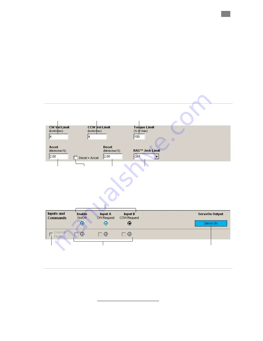
Enter motor
acceleration rate.
Check here to set
motor deceleration
rate to same value
as acceleration rate.
Soft Inputs and LEDs
emulate
hardware inputs. For use only
when Soft Controls are active.
Caution: motor may spin when
enabled.
Enter motor
deceleration rate.
Hardware Input Status LEDs
Light = Input asserted (on)
Dark = Input de-asserted (off)
Displays output status.
HLFB modes supported:
>Servo On
>AllSystemsGo
>Speed Output
Check to turn on Soft
Controls. Override cannot
be activated when ClearPath
is hardware enabled.
Enter value (1-100) to limit
peak torque capability of
motor as a % of motor’s
maximum peak torque.
Set jerk limit. Higher values result in
smoother, more gradual transitions
between move segments of differing
acceleration; however, overall move
time is increased.
Enter max velocity
(limit) for CW rotation.
Enter max velocity
(limit) for CCW rotation.
om the previous
move request. Thus, if the motor was spinning in the CW direction when the move was
canceled, ClearPath will only respond to a CCW move request.
4 In this scenario, the next move request must be in the opposite direction fr
T
EKNIC
,
I
NC
.
F
AX
(585)784-7460
V
OICE
(585)784-7454


