C
L E A R
P
A T H
U
S E R
M
A N U A L
R
E V
.
1 . 9 7
3 2
S
COPE
D
ISPLAY AND
S
COPE
C
ONTROLS
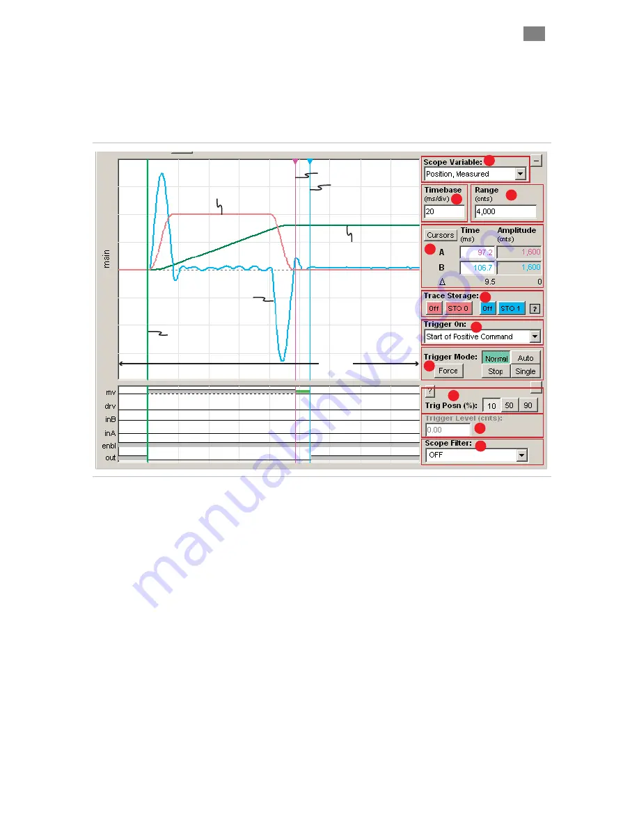
The MSP Scope display is modeled after that of a typical hardware
such, it has 10 major vertical divisions on the time axis
oscilloscope; as
and 8 major horizontal divisions on the amplitude axis.
Stored Trace (STO 0)
Commanded Velocity
Trigger Point
Currently at 10% position
Stored Trace (STO 1)
Actual Torque
Live Trace
Measured Position
‘A’ Cursor
‘B’ Cursor
200mS
(20 mS/division x 10 divisions)
Click and drag
to position cursors
2
3
4
5
6
7
1
8
9
10
MSP Scope
1
The Scope Variable drop down menu lets you select any of 12
ClearPath motion control variables to display. These variables include
Tracking Error, Commanded Velocity, Actual Torque, Actual Velocity,
Velocity Error, Commanded Torque, SGN (sign of velocity), Measured
Position, Commanded Jerk, Commanded Acceleration, Max Phase
Voltage, and Torque Error.
just the scale of the time axis (think
vision. This allows you to control how
the Scope Display. For example, if the
the full
on).
e scale of the amplitude axis
to control how a waveform fits
ve the green
t
Position and the Range is set to 4000 counts.
horizont
s (+)4000 counts, and the bottom line represents
(-)
s.
4
Cursor controls allow you to drag the two vertical cursors around on
the main scope display and view time and amplitude measurements in
2
The Timebase text box lets you ad
Cartesian X-axis) in units of mS/di
a waveform fits horizontally on
Timebase is set to 20mS per division (as in the figure above)
ns x 20mS/divisi
horizontal range of the scope is 200mS (10 divisio
3
The Range text box lets you change th
(think Cartesian Y-axis). This allows you
vertically on the Scope Display. For example, in the figure abo
race represents Measured
This means the center horizontal line represents 0 counts, the top
al line represent
4000 count
T
EKNIC
,
I
NC
.
F
AX
(585)784-7460
V
OICE
(585)784-7454


