C
L E A R
P
A T H
U
S E R
M
A N U A L
R
E V
.
1 . 9 7
2 1
Tip: To make a simple manual controller—for ClearPath modes that don’t
require pulse trains—wire a few toggle switches and a 9V battery to the
ClearPath inputs (see diagram on previous page.) The inputs are
internally current limited, so there’s no need for external current limiting
resistors.
M
INIMUM
I
NPUT
C
URRENT
R
EQUIREMENT
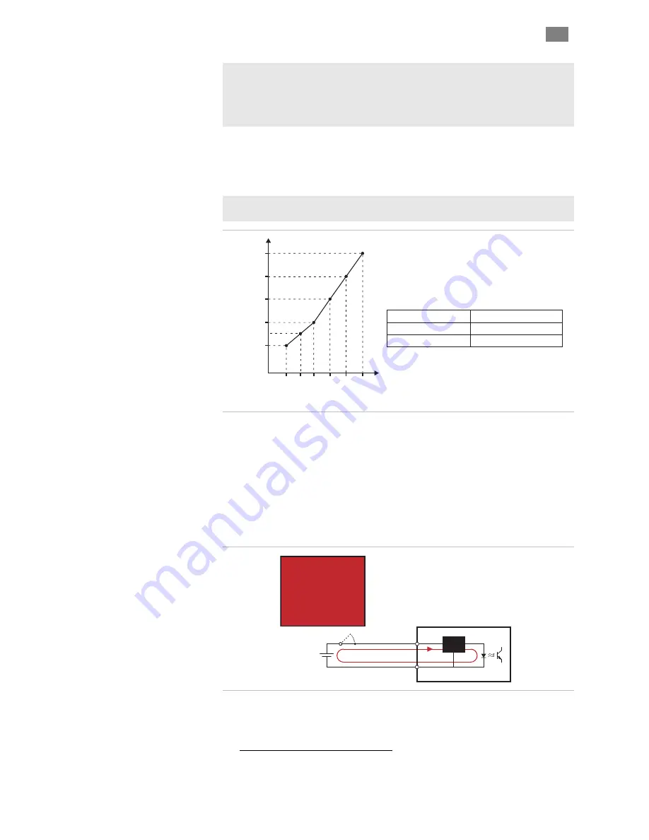
Devices wired to ClearPath inputs must be able to source/sink a minimum
current value as described in the graph below.
Tip: if your device (PLC, microcontroller, power supply) can source or
sink at least 12mA, you’re covered for all typical input voltages.
Voltage at
ClearPath Input
Minimum Input
Current Required
5 VDC
8 mA
12 VDC
9 mA
24 VDC
12 mA
Min. Input Current (mA)
5 9 12 16
24
Input Voltage (VDC)
12
10
11
9
8
20
Minimum Input Current
I
NPUT
d
E
NABLE
The Enable Input controls power to the motor coils. When a ClearPath is
powered up and the Enable Input is asserted (i.e. 5–24VDC is present at
the input) the motor windings energize and ClearPath is able to respond
to control signals at Inputs A and B. When Enable is de-asserted (0 volts
applied) power to the motor coils is shut off and the motor cannot respon
to user inputs
2
.
When Enable is asserted:
•
Motor windings energize
•
Motor will respond to inputs
•
Shaft is able to spin
WARNING!
An enabled motor can
and will spin in
response to input
states. Always keep
fingers, clothing, and
other objects clear of
motor shaft.
Enable
+
Enable
-
Current
Limiter
5-24VDC
ClearPath Enable Input
Input.
2 Exception: when ClearPath is set to “Spin on Power Up” mode, the motor shaft can move
as soon as main DC power is applied, regardless of the state of the Enable
T
EKNIC
,
I
NC
.
F
AX
(585)784-7460
V
OICE
(585)784-7454


