TeeJet AEROS9040 User Manual Download Page 37

33

98-01504-ENUS R2

Aeros 9040 Field Computer

ADDITIONAL IMPLEMENT OPTIONS

TIP SELECTION 

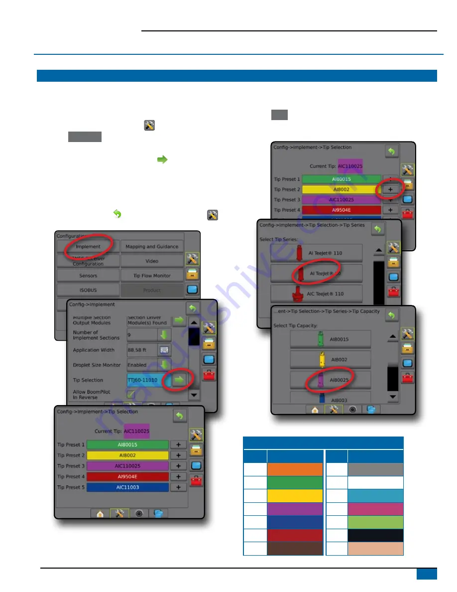
When the system includes a Pressure Sensor Interface Kit (PSIK), Tip 

selection is used to select the type of sprayer tip (series and capacity) 

for determining droplet size information.
1.  Press CONFIGURATION side tab 

.

2.  Press 

 Implement 

.

◄Current tip section is shown in the information box

3.  Press Tip selection NEXT PAGE arrow  .
4.  Select from:

►Tip preset 1-5 – selects up to five (5) tips for quick recall, and 

selected the current tip for determining droplet size information

►Current tip – displays the current tip

5.  Press RETURN arrow   or CONFIGURATION side tab 

 to 

return to the main Configuration screen.

Preset

Tip presets allow saving of up to five tips for quick recall.
1.  Press 

    +    

.

2.  Select a TeeJet tip series.
3.  Select tip capacity.

Tip Sizes and Associated Colors

Established Tip Capacities and Colors

Size

Color

Size Color

01

Orange

06

Gray

015

Green

08

White

02

Yellow

10

Light Blue

025

Purple

12

Telemagenta

03

Blue

15

Light Green

04

Red

20

Black

05

Brown

30

Beige

Summary of Contents for AEROS9040

Page 1: ...U S E R G U I D E AEROS9040 Software version 4 31...

Page 2: ...mplement Type 4 Section Numbers 5 Straight 5 Spreader TeeJet 6 Lateral Implement Offset Distance Adjustment 7 GNSS Offset Adjustment Calculation 7 Lateral Implement Offset Adjustment 8 4 Set Up the Ma...

Page 3: ...AR 26 GUIDANCE FEATURES DETAILS 27 A Nudge Feature 27 Azimuth Degree 27 Return to Point 28 Next Guideline Feature 29 REFRESH GNSS POSITION 29 BOOMPILOT 30 No Section Control Module 30 ISOBUS Sprayer 3...

Page 4: ...by failure to adhere to the following safety requirements As the operator of the vehicle you are responsible for its safe operation The Aeros 9040 in combination with any assisted auto steering devic...

Page 5: ...utton Unit Setup RealView Camera Full Screen Video View ISOBUS Universal Terminal System Setup System Setup is used to configure the console the machine and its implements Four side tabs access option...

Page 6: ...Port and PRN and other GNSS parameters and to view GNSS status information 1 Press SYSTEM SETUP bottom tab 2 Press CONFIGURATION side tab 3 Press GNSS Receiver Configuration 4 Select from GNSS Type s...

Page 7: ...s with ISOBUS Sprayer Spreader Setup Single Section Setup Single Section Setup is used when a SmartCable Section Driver Module SDM or Switch Function Module SFM is not on the system that is no sectio...

Page 8: ...re Sensor Interface Kit used to enable droplet size monitoring for up to five sprayer tips Tip Selection Straight Implement Type completed on the ISOBUS ECU used to display the type of sprayer tip as...

Page 9: ...line Offset Direction displays if the implement is located in front of forward or behind backward the GNSS antenna while facing in the machine s forward direction Implement In line Offset Distance me...

Page 10: ...Distance defines the lateral distance from the centerline of the machine to the center of the implement Overlap used to define the amount of overlap allowed when using automatic boom section control...

Page 11: ...ws overlaps and gaps adjustments may need to be made to the assisted auto steering settings GNSS Offset Adjustment Calculation To calculate a GNSS offset adjustment using the same guideline 1 Create a...

Page 12: ...and pass 5 Divide the measured distance in half This difference will be the offset adjustment 6 Increase or decrease the offset distance as needed dependent on where the field application overlap occu...

Page 13: ...that is perceived as zero error 4 Select user entry location from the Mapping Locations drop down options 5 Press MAPPING LOCATION NEXT PAGE arrow to set up the selected specific mapping location opt...

Page 14: ...Client information farm information field information and prescription maps can only be inputted using Fieldware Link A job name can only be edited using Fieldware Link A user can duplicate jobs for...

Page 15: ...allows live video input to be displayed instead of a computer generated image 6 1 mph 7 62 ac 0 0 55 psi 6 1 mph 7 62 ac Mark A 6 1 mph 7 62 ac 0 0 To choose a guidance mode 2 Press NAVIGATION AND GU...

Page 16: ...uired to map a boundary Using Data Job Data Manage or with Fieldware Link a user can duplicate and edit jobs for reuse of boundaries for different applications over the same field Application is not r...

Page 17: ...ete the boundary Figure 14 Exterior Boundary 0 00 ac 0 0 mph 2 32 ac 7 2 mph 3 68 ac 7 2 mph Figure 15 Add Interior Boundary 4 55 ac 7 2 mph Delete Last Marked Boundary Use DELETE BOUNDARY icon to del...

Page 18: ...ctive Trip Count Number should show TC 20 00 gal ac 66 00 ac Mark A Guidance Screen Options When a ISOBUS Electronic Control Unit ECU sprayer or spreader control is integrated into the implement rate...

Page 19: ...ATION OPTIONS tab 3 Select from Target Rate Percentage Increase establishes the required boost percentage step increase Target Rate Percentage Decrease establishes the required boost percentage step d...

Page 20: ...rates applied area and overlap Blue one application Red two or more applications 27 00 ac 10 0 mph Mark A Polygons Map Polygon map shows all mapped polygons Guidelines Blue polygon boundary line 27 00...

Page 21: ...established on the ISOBUS ECU using the ISOBUS UT The current Target rate is selected and boosted using the ISOBUS Operation screen on the UT Boosting can also be controlled using the Vehicle view scr...

Page 22: ...displayed in the application area From this screen all setup boundary polygon mapping application and navigation options can be accessed via the options tabs on the right side of the screen 10 0 mph...

Page 23: ...Guidance Straight AB guidance provides straight line guidance based on A and B reference points The original A and B points are used to calculate all other parallel guidelines NOTE Offset to adjacent...

Page 24: ...will not initiate NextRow Guidance NextRow guidance indicates where the NextRow is located and provides guidance at row ends to the next adjacent row When the operator marks the end of the row and be...

Page 25: ...vigation and Guidance Options On any guidance screen displays navigation options including guidance modes guideline options return to point options refresh GNSS BoomPilot toggle curved lookahead toggl...

Page 26: ...on Resets the ClearPath filter in the OEMStar receiver Boundary and Polygon Options On any guidance screen displays exterior boundary interior boundary and polygon options 12 deg 13 0 0 55 psi Exterio...

Page 27: ...gon has been established 12 deg 13 0 0 55 psi Coverage map shows areas covered by the implement regardless of whether product was applied Polygon map shows all mapped polygons Prescription map shows p...

Page 28: ...and guidance over video options 12 deg 13 0 0 Video camera select selects one of up to eight camera views if a Video Selection Module VSM is attached Split camera view selects one of two sets of four...

Page 29: ...plied including double coverage areas Application Time displays the total time application is active during the current job Time displays the current time based on the selected time zone Swath Number...

Page 30: ...nside exterior bounded area No icon no boundary established exterior or interior Assisted Auto Steering Status Green engaged actively steering Yellow enabled all conditions have been met to allow for...

Page 31: ...ary circle North 0 East 90 South 180 West 270 Azimuth Degree guidance projects a guideline between the current vehicle position the A point and a B point set 100 meters away along the entered azimuth...

Page 32: ...3 Press ADD POINT icon 8 19 am 1 7 mph 8 21 am 1 7 mph Delete the Return Point To delete the established return point 1 Press NAVIGATION AND GUIDANCE OPTIONS tab to display navigation options 2 Press...

Page 33: ...navigation options 2 Press NEXT GUIDELINE icon Toggle between all guidelines by pressing the NEXT GUIDELINE icon again 13 7 2 mph 0 0 To view which guideline is active press the Guidance mode icon on...

Page 34: ...STEM SETUP bottom tab 2 Press CONFIGURATION side tab 3 Press Implement 4 Set BoomPilot icon to Enable NOTE BoomPilot start mode setting will make no difference in the function of this option To switch...

Page 35: ...Manual status bar icon will change to red 3 Turn master switch or individual section switches On Off With an ISOBUS Implement Status Module ISO ISM All ISOBUS rate control configurations should be set...

Page 36: ...f position With TeeJet Section Control Module And Switchbox or ISM SmartCable Section Driver Module SDM or Switch Function Module SFM and a switchbox or Implement Status Module ISM is present NOTE The...

Page 37: ...m Tip preset 1 5 selects up to five 5 tips for quick recall and selected the current tip for determining droplet size information Current tip displays the current tip 5 Press RETURN arrow or CONFIGURA...

Page 38: ...able on the operation screens Setup Enable Disable DSM 1 Press CONFIGURATION side tab 2 Press Implement 3 Press Droplet Size Monitor 4 Select if Droplet Size Monitor is enabled or disabled 5 Press RET...

Page 39: ...ication categories always remember that a single tip can produce different droplet size classifications at different pressures A tip might produce medium droplets at low pressures while producing fine...

Page 40: ...atic section control and mapping that is correct for reverse machine movement Speed on the Guidance bar will turn red while traveling in reverse Figure 24 Traveling Forward 1 14pm 7 2 mph 0 0 Figure 2...

Page 41: ...ance screens BoomPilot Icon used to establish if the BoomPilot icon is available in the navigation and guidance options on the guidance screens for manually controlling BoomPilot Enable BoomPilot Icon...

Page 42: ...he tip flow balance process 4 Press RETURN arrow or CONFIGURATION side tab to return to the main Configuration screen ISOBUS SPRAYER OFFSETS Connection point and implement offsets are used to enter th...

Page 43: ...tance from the centerline of the machine to the center of the rear axle Implement In line Offset Direction same direction as Aeros Connection Point In line Offset Direction Implement In line Offset Di...

Page 44: ...tion Implement Lateral Offset Distance same value as on Aeros Connection Point Lateral Offset Distance Figure 31 Front Mount Figure 32 Rear Mount Center of the GNSS antenna Connection Point Connection...

Page 45: ...Point Lateral Offset Distance Figure 33 Always Rear Mount Center of the GNSS antenna Connection Point Center of the front axle of the trailed implement Connection Point In line Offset Direction Distan...

Page 46: ...k jobs can be ported back to a USB storage device to be moved back onto the console internal storage for use Manage when in advanced job mode allows the creation of a new empty job copying of a select...

Page 47: ...e Link machine settings can be ported back to a USB storage device to be moved back onto the console internal storage for use Manage allows the creation of a new empty machine settings the copying of...

Page 48: ...05968 Harness Aeros UT TJT Junction Box Only OR 45 09031 Aeros Junction Box COBO IBBC Extension Cable 45 09023 20 ft 6 m 45 09024 30 ft 9 m 45 09025 40 ft 12 m to Ground Speed to Spinner RPM Sensor to...

Page 49: ...ket Kit Generic 45 05986 Ethernet Interface RJ5 to Conxall 32 04020 Foot Switch 45 10166 UniPilot Pro Harness 91 05023 UniPilot Pro Electric Steering Device 65 05251 Bracket SCM Pro Flat 91 05023 UniP...

Page 50: ...HNOLOGIES PROVIDES THIS MATERIAL AS IS WITHOUT WARRANTY OF ANY KIND EITHER EXPRESSED OR IMPLIED NO COPYRIGHT LIABILITY OR PATENT IS ASSUMED IN NO EVENT SHALL TEEJET TECHNOLOGIES BE LIABLE FOR ANY LOSS...

Reviews: