


19
98-01504-ENUS R2
Aeros 9040 Field Computer
RealView Guidance
RealView guidance allows live video input to be displayed instead of a computer-generated image. From this screen all setup, boundary,
polygon and navigation options can be accessed via the tabs on the right side of the screen. To adjust the camera view [reverse, upside
down], go to Setup-> Configuration-> Video.
►Single Camera – a single camera is directly attached to the console
►Video Selection Module – if a Video Selection Module (VSM) is installed on the system, two (2) video options are available:
• One camera view – one of up to eight camera inputs can be selected to change the view of the video input.
• Split camera view – one of two sets of four camera inputs (A/B/C/D or E/F/G/H) can be selected to divide the screen into four separate
video feeds.
27.00
ac
10.0
mph
0.0
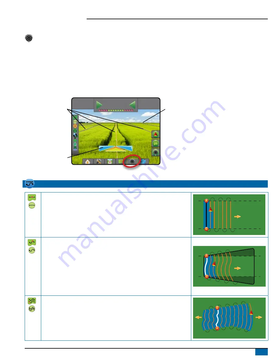
Status Bar
Guidance Bar
Navigation Guidelines
Steering Angle
Navigation and Guidance Options tab
Horizon Line
Boundary and Polygon Options tab
RealView Options tab
GUIDANCE MODES
Straight AB Guidance
Straight AB guidance provides straight-line guidance based on A and B reference
points. The original A and B points are used to calculate all other parallel guidelines.
NOTE: Offset to adjacent guidelines will be calculated using the guidance width: see
“Configuration-> Mapping and guidance” in the System setup chapter.
Curved AB Guidance
Curved AB guidance provides guidance along curved lines based on an initial AB
reference line. This initial baseline is used to calculate all other guidelines.
NOTE: Curved guidance is recommended not to exceed 30° within the AB guideline.
Offset to adjacent guidelines will be calculated using the guidance width: see
“Configuration-> Mapping and guidance” in the System setup chapter.
HINT: While working in a bounded area, the guidance pattern extending beyond the
established AB points will be straight-line guidance.
Adaptive Curve AB Guidance
Adaptive Curve guidance* provides guidance along a curved line based on an initial
AB reference line where each adjacent guideline is drawn from the projected guidance
width and heading.
NOTE: Offset to adjacent guidelines will be calculated using the guidance width: see
“Configuration-> Mapping and guidance” in the System setup chapter.


