Convection gas oven rev. 0___________________________________ MODD. EKF 1111G E UD – EKF 1064G E UD
_________________________________________________________________________________________ page. 11
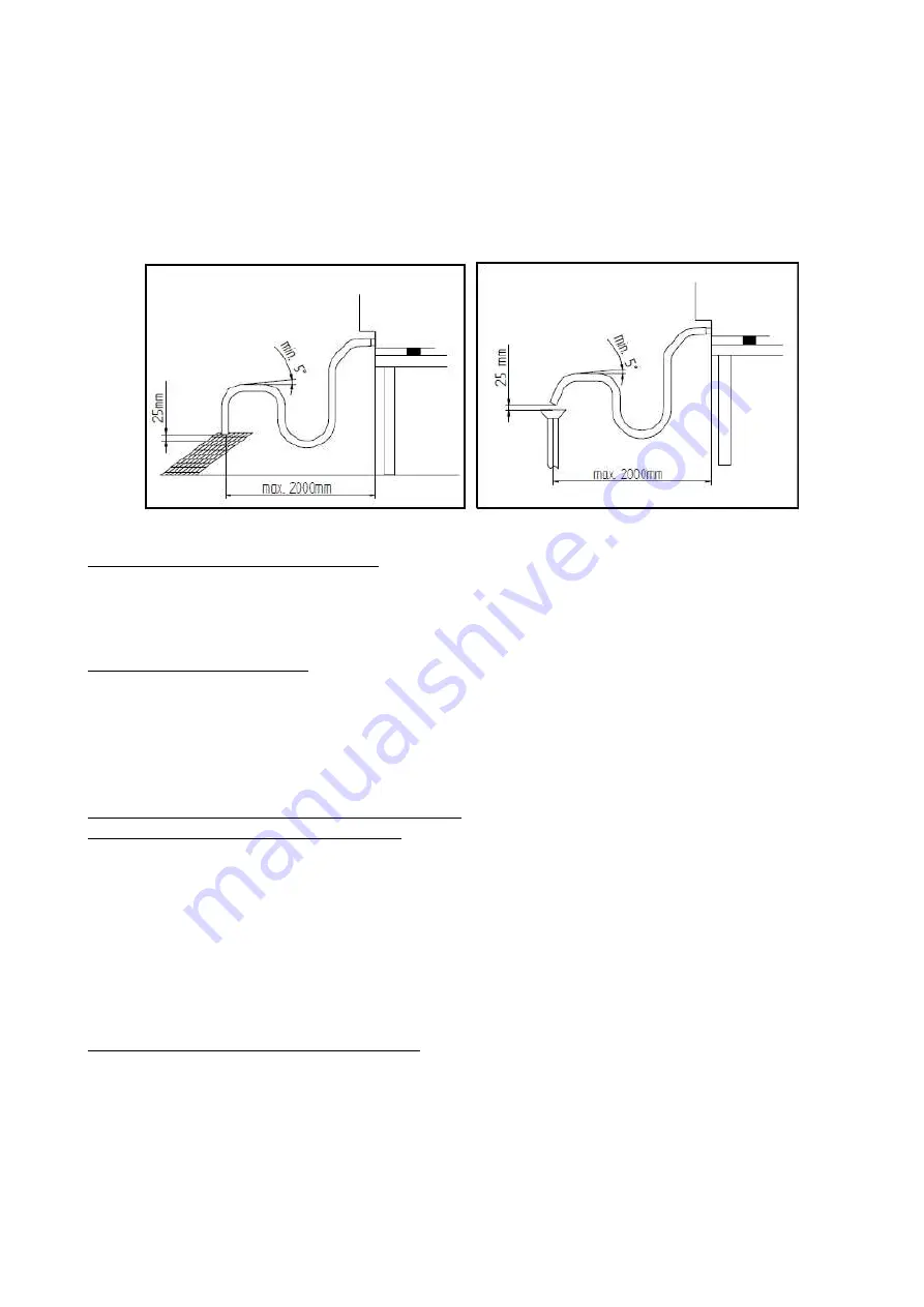
Furthermore, the minimum "air gap" must be 25 mm (distance between the drain pipe from
the appliance and the cup of the drain duct pipe). In any case, for reasons of compliance with
health regulations in force, the piping connected to the drain pipe of the appliance must not be
in direct contact with the drain point. It is recommended to connect the appliance's drain to the
grey water network through an adequate syphon, in order to stop steam from coming out of
the drain. The connection to drain water must be done separately for each appliance; in case of
several appliances connected to the same drain pipe, ensure the pipe is suitably sized to assure
regular drainage with no hindrances.
FIG. 4
FIG. 5
2.11 Thermal breaker safety devices
The appliance is equipped with a manually reset safety thermostat, to protect against excessive
and hazardous overheating which might accidentally occur inside it. In the event of tripping the
device interrupts power supply to the appliance and the incoming gas to the burner.
2.12 Disposing of the oven
The appliance is made using recyclable raw materials and contains no toxic or harmful
substances for people or the environment. The appliance, and its packaging, must be disposed
of in conformity with the current regulations in force in the place of installation. The various
materials used for its construction must be separated and delivered to the specialised waste
disposal centres. In all cases the environment protection regulations must be strictly adhered to.
3. START-UP (for installation technician)
3.1 Check of nominal thermal capacity
The nominal thermal capacity must be verified by an authorised technician or by the gas supply
Body, observing the information in this use manual. This check must be performed for new
installations, adaptation to another type of gas and during all extraordinary maintenance jobs.
There is no other possibility of adjusting the nominal thermal capacity – this is done by
measuring correct connection pressure and checking if the injector being used is of appropriate
diameter. The nominal thermal capacity is controlled by using a gas meter and a chronometer.
The exact volume of gas that must flow through per time unit can be obtained from the
technical specifications table. This value must be maintained in the specified range, the
permissible tolerance being
±
5%.
3.2 Check of connection pressure (Fig. 6)
The connection pressure is measured, with the unit working, using a pressure gauge for liquids
(for instance a liquid-level gauge with a minimum resolution of 0,1 mbar). To carry out this test,
remove the back of the unit and connect the “T” hose of the “M” gauge to the “P” inlet
pressure tapping point of the gas solenoid valve, after unscrewing the tapping point screw.


