


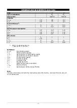


GENERAL INFORMATION
- 9 -
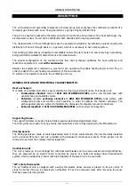
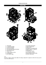
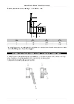
STRUCTURE
1
2
3
4
5
5
6
7
8
9
10
11
11
17
18
20
18
19
15
16
13
12
14
1)
Smoke pipe
2)
Combustion chamber
3)
Front fume manifold
4)
Rear fume manifold
5)
Heat exchanger inspection shutters
6)
Fume exhaust fitting
7)
Burner head
8)
Flame inspection window
9)
Centrifugal fan
10)
Fan electric engine
11)
Condensate drain fitting
12)
Smoke discharge Kit
13)
Lower struts
14)
Outside air controlling shutter
15)
Gravity shutter on outside air
16)
Protection net
17)
Overpressure shutter
18)
Fire protection shutter
19)
Recirculation air suction fitting
20)
Hot air outlet fitting
Note:
In order to make the internal parts visible, the drawing represents the equipment without the housing of the
burner and electrical panel.
Summary of Contents for WIMBLEDON 145
Page 26: ...INSTALLATION AND SETTING INSTRUCTIONS 26 WIRING DIAGRAM Cod 10023495 TC Wiring diagram TYPE 1...
Page 27: ...INSTALLATION AND SETTING INSTRUCTIONS 27...
Page 28: ...INSTALLATION AND SETTING INSTRUCTIONS 28 Wiring diagram TYPE 2...
Page 29: ...INSTALLATION AND SETTING INSTRUCTIONS 29...


