


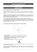


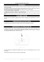


INSTALLATION AND SETTING INSTRUCTIONS
- 31 -
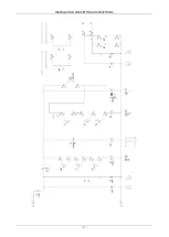
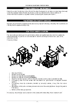
Legend:
Q1
Main switch
LM 1-2
Safety thermostat with manual reset
TR 1-2
Safety thermostat with automatic reset
ST 1-2
Fire shutter switch
SC
Condensate safety switch
TZ
Fan start timer
FV
Fuses
FA
Fuses
FB
Fuses
KM 1-2
Contactor
RT 1-2
Thermal relay
RB
Burner relay
LX
Alarm relay
TA
Appliance start-up
V
Voltage absence light
V
Alarm light
FL 1-2
Flow switch
M 1-2
Burner engine
RFW 40
Modulating gas burner regulator
X4
4-pole terminal of the modulating gas burner
MB
Terminal of the modulating gas burner
X7
7-pole terminal of the modulating gas burner
SONDA
Temperature probe of the modulating gas burner
A more detailed copy of the wiring diagram is available on the air treatment unit as well
If you have any doubt, do not carry out any operation on the appliance. Ask the Manufacturer
for clarifications.
Pursuant to electric installation Standards, the equipment must have a device that guarantees
its disconnection from the supply mains with a contact separation that provides full
disconnection under overvoltage category III (EN 60335-1 Standard)
Summary of Contents for WIMBLEDON 145
Page 26: ...INSTALLATION AND SETTING INSTRUCTIONS 26 WIRING DIAGRAM Cod 10023495 TC Wiring diagram TYPE 1...
Page 27: ...INSTALLATION AND SETTING INSTRUCTIONS 27...
Page 28: ...INSTALLATION AND SETTING INSTRUCTIONS 28 Wiring diagram TYPE 2...
Page 29: ...INSTALLATION AND SETTING INSTRUCTIONS 29...


