


INSTALLATION AND SETTING INSTRUCTIONS
- 18 -
The chimney flue must guarantee minimum depression, as provided for by Technical Standards in force,
taking into consideration that the pressure is “zero” at the joining point with the smoke duct.
Non-insulated exhaust ducts are a source of potential hazard.
Inadequate or wrongly sized chimney flues or smoke ducts may amplify the combustion noise and negatively
influence the combustion parameters.
The joints must be sealed with materials resistant to thermal and chemical stress caused by combustion
products.
Crossings through walls and/or roofs, if any, must be performed up to standard, in order to avoid hazards of
fire and/or water infiltration.
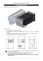
CONDENSATE DRAIN CONNECTION
The condensate drain system should comply with the relevant European, National and Local Standards, and
the need for a neutralisation treatment should be checked.
We provide the following instructions, for information purposes:
•
the condensate drain system should be dimensioned and made in a such a way that liquids can flow out,
without leaking;
•
all condensate drain unions should be independently connected, and they should not be combined in one
duct;
•
smokes must be prevented from being discharged through the condensate drain system; therefore a
syphon should compulsorily be installed.
•
Condensate that may accumulate in the chimney flue, must never be permitted to backflow into the
equipment. A specific condensate drain must be created;
•
The system should have a proper gradient. Pipes should not be installed at the same level of the machine
nor in counter-inclination.
•
In case of connection to the domestic sewage net, a suitable trap or equivalent device is to be used in
order to prevent any backflow from the sewage net;
•
The system must be made in a way as to prevent the freezing of the liquids it contains, in all
expected operating conditions;
•
The system is to be provided with a device that stops the burner in case of accidental clog of the
condensate drain system, in order to avoid hazard situations or unhealthy combustion;
Summary of Contents for WIMBLEDON 145
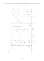
Page 26: ...INSTALLATION AND SETTING INSTRUCTIONS 26 WIRING DIAGRAM Cod 10023495 TC Wiring diagram TYPE 1...
Page 27: ...INSTALLATION AND SETTING INSTRUCTIONS 27...
Page 28: ...INSTALLATION AND SETTING INSTRUCTIONS 28 Wiring diagram TYPE 2...
Page 29: ...INSTALLATION AND SETTING INSTRUCTIONS 29...


