TE Connectivity 528008-4, Operating Instructions Manual
The TE Connectivity 528008-4 Operating Instructions Manual is available for free download at manualshive.com. This comprehensive manual provides detailed guidance on how to operate and maintain the product effectively. Download your copy today and ensure you get the most out of your TE Connectivity 528008-4 device.
Share
Download


Reviews:
No comments
Related manuals for 528008-4

RHP-350
Brand: Paslode Pages: 32

1752786-1
Brand: TE Connectivity Pages: 6

PSG12 POWER PLUS
Brand: Milwaukee Pages: 46

MT2-1500N
Brand: Matatakitoyo Torque Tools Pages: 2

DMH 250/1
Brand: EINHELL Pages: 32

192CDLR
Brand: Roach Conveyors Pages: 19

1901820-1
Brand: Tyco Electronics Pages: 4

LOCK/JIG
Brand: TREND Pages: 19

74E
Brand: Carpenter MFG Pages: 8
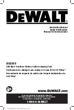
DCE350
Brand: DeWalt Pages: 48

101-1008
Brand: shars Pages: 46

3110470
Brand: Clarke Pages: 16

PrimeLock
Brand: entegris Pages: 8

GS4EH
Brand: Panduit Pages: 2

GS2B
Brand: Panduit Pages: 2

BlackFin CT-2940/STBT
Brand: Panduit Pages: 12

33858
Brand: Eastwood Pages: 4

G2752
Brand: Garden Gear Pages: 8


