


Icon Setup
42
DB6 Single / Multi / AES – Firmware version 1.30
Icon Setup
This chapter covers screens and parameters of
the TC Icon software not directly related to the
day-to-day operation of your DB6.
Accessing the Icon Setup pages
– If it isn’t already, switch the TC
Icon software to Base mode by
clicking the Icon symbol in the
upper left corner of the window
– see “TC Icon modes: Base and
Device operation” on page 20.
In Base Mode, you will see the
Select, Auto and Setup tabs on
the upper edge of the TC Icon
window.
– Select Setup.
– Select one of the pages described in the fol-
lowing sections of this manual.
Info page
On this page, the version number of the currently
installed TC Icon software is displayed.
To update the TC Icon software, please refer to
the “Updating DB6 software” on page 19 sec-
tion of this manual.
Devices page
Use this page to detect, control and assign the
devices in your local network.
Detect button
Click the “Detect” button to scan the network for
connected devices. All detected devices will ap-
pear in the list.
If you encounter problems when detecting con-
nected devices, please refer to “Networking ba-
sics and troubleshooting” on page 16.
Assigning devices to
the available slots
You need to assign a device to a slot of the
TC Icon software to control it.
Each instance
of the TC Icon software can control up to eight
different devices.
– Select a device from the list on the left side of
the screen.
– Click one of the eight slots on the right side
of the screen to assign the selected device to
this slot.
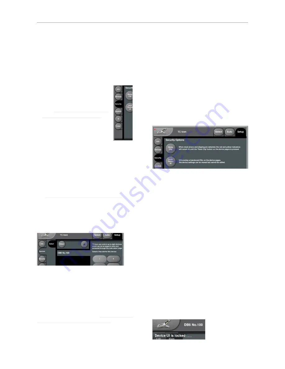
Security page
On the security page, you can set several fea-
tures regarding device readouts and operation.
Sticky Clip button
Click the Sticky Clip button to activate or deacti-
vate the Sticky Clip feature.
When the Sticky Clip feature is activated (button
highlighted) and clock errors or clippings are de-
tected in a device, the red and yellow warning in-
dicators will remain lit until the user presses “Re-
set Clip” button. This feature ensures that clock
errors or clippings do not go unnoticed.
Lock Device UI button
Click the Lock Device UI button to lock or unlock
the user interfaces of the devices controlled by
the TC Icon software.
When the Lock Device UI feature is activated
(button highlighted), the user will be able to
see
the settings of the currently selected device, but
he cannot
change
them. This will be indicated by
a semi-transparent overlay and a “Device UI is
locked” message on all device-related screens.
Summary of Contents for DB6
Page 2: ......
Page 4: ......
Page 41: ...Updating DB6 firmware English Manual 2014 03 05 37...
Page 73: ...Technical specifications English Manual 2014 03 05 69...
Page 74: ...Technical specifications 70 DB6 Single Multi AES Firmware version 1 30...
Page 75: ...Technical specifications English Manual 2014 03 05 71...
Page 76: ...Technical specifications 72 DB6 Single Multi AES Firmware version 1 30 Item No E60537014...


