


Getting to know DB6
English Manual (2014-03-05) 13
Yellow
There has been silence for
more than five seconds, or the
LM6 algorithm has detected a
“High Loudness” state.
Signal LED
DB6 Single
has one Signal LED, while
DB6 Multi
has three Signal LEDs – one for each of the up to
three cards/engines in the device.
The Signal LEDs indicate if audio stream are re-
ceived and processed by DB6.
LED color /
indication
Status
Off
No audio signal (above
-70 dBFS) has been detected.
Green
An audio signal above
-70 dBFS has been detected.
Yellow
An audio signal above -1 dBFS
has been detected.
Front panel reset button
The Reset button on the front panel can be used
to reset the IP address of a DB6 unit or to reset
Ethernet communication between DB6 and a
computer when a communication error has oc-
curred.
Resetting the IP address
of a DB6 unit
It may be necessary to reset the IP address of a
DB6 unit. To do so, proceed as follows:
– Switch off DB6 by disconnecting both power
supplies.
– Insert a straightened paper clip or a similar
object into the “Reset” hole on the front panel
until it touches the button behind the panel.
– Boot the DB6 by connecting one or both pow-
er supplies while still holding the straightened
paper clip onto the Reset button.
DB6 will boot using its default IP address.
The default IP address is 192.168.1.[xx], where
[xx] is the last two digits of the device’s serial
number as printed on its back.
Resetting Ethernet communication
It may be necessary to reset Ethernet communi-
cation between DB6 and a computer
during op-
eration.
To do so, proceed as follows:
– During operation, insert a straightened paper
clip or a similar object into the “Reset” hole
on the front panel until it touches the button
behind the panel, and press the button for
approximately 5 seconds until the LEDs start
blinking.
This will reset Ethernet communication with-
out interrupting audio streams.
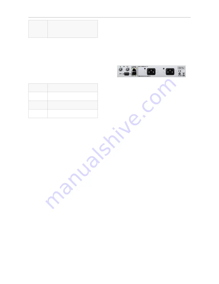
Back panel connectors
Back panel connectors on a DB6 Single
PSU (2 x)
DB6 has two C13 type power inlet sockets. The
dual power inlets provide extended operational
security and stability. They accept 100 to 230
Volts AC at 50/60 Hz.
If possible, connect these two power sockets to
two
independent
power sources to minimize the
risk of power loss.
Due to the redundant design, DB6 will still be
fully operational when one of the two power sup-
plies fails. However, to ensure maximum security
and stability, you should address the issue and
investigate the cause of the error indication at
the first given opportunity.
In case of
complete
power loss, the device is
hardware-bypassed via relays, ensuring that no
signal loss occurs.
Ethernet (2 x / 6 x)
DB6 is equipped with 32 bit Ethernet inter-
faces fully compliant with the IEE 802.3u stan-
dard, supporting 10 and 100 Mbit/s (100Base-TX
ports).
DB6 Single
and DB6 AES have two Ethernet
ports, while
DB6 Multi
has either two, four or six
Ethernet ports, depending on the number of 3G
Transmission cards installed.
Connect a computer running TC Icon software
or a hardware TC Icon device to one of these
ports using a “straight-through” cable with 8P8C
modular connectors (“RJ45”). A “crossover” type
cable is
not
required.
Summary of Contents for DB6
Page 2: ......
Page 4: ......
Page 41: ...Updating DB6 firmware English Manual 2014 03 05 37...
Page 73: ...Technical specifications English Manual 2014 03 05 69...
Page 74: ...Technical specifications 70 DB6 Single Multi AES Firmware version 1 30...
Page 75: ...Technical specifications English Manual 2014 03 05 71...
Page 76: ...Technical specifications 72 DB6 Single Multi AES Firmware version 1 30 Item No E60537014...


