6 – Modules
q
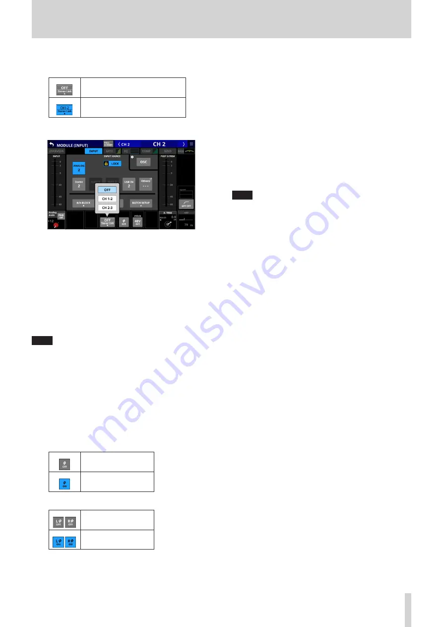
Stereo Link button (CH 1–40 modules only)
o
This shows the stereo link setting of the input channel.
Stereo linking is off
Stereo linking is on
o
Tap this button to open the Stereo Link setting window.
Linking with either module to the left or right is possible
except for channels 1 and 40.
w
16ch BLOCK button (Sonicview 16, CH 1–32 modules
only) or 24ch BLOCK button (Sonicview 24, CH 1–40
modules only)
When the LOCK/UNLOCK button (
3
) is set to “UNLOCK”, tap
this button to open a window where the input sources of
16 (Sonicview 16) or 24 (Sonicview 24) channels can be set
at the same time. (See “Setting input sources for multiple
channels at the same time in blocks” on page 65.)
Change settings for multiple designated channels at the
same time.
NOTE
i
This cannot be used when the LOCK/UNLOCK button (
3
) is
set to “LOCK”.
i
If routing operation is set to “LOCK” on another touchscreen
while a multiple setting window is open, it will close
automatically.
e
Phase button
Use this to change the phase of the signal for the selected
module.
Tap this button to reverse the phase of the selected module
signal.
o
Phase button display when the Stereo Link setting is off
for the selected CH 1–40 module
Normal
Reversed
o
Phase button display for stereo modules
Normal
Reversed
r
48V button
o
This shows the phantom power setting status when the
input source of the selected module is “ANALOG” or “SB-
16D connected by built-in Dante”.
o
Touch and hold the 48V button to turn phantom power
(+48V) on/off. (Default: OFF)
When phantom power is on, the button will be
highlighted.
t
BATCH SETUP button
When the LOCK/UNLOCK button (
3
) is set to “UNLOCK”, tap
this button to open a window where the input sources of a
range of channels can be set at the same time. (See “Setting
inputs sources for multiple channels at the same time in
batches” on page 66.)
Change settings for multiple designated channels at the
same time.
NOTE
i
This cannot be used when the LOCK/UNLOCK button (
3
) is
set to “LOCK”.
i
If routing operation is set to “LOCK” on another touchscreen
while a multiple setting window is open, it will close
automatically.
y
D.TRIM knob
o
Use this to adjust the digital trim value.
Range: -50.0 dB - +20.0 dB (default: 0.0 dB)
Turn LCD knob 7 (lit red) to adjust it.
o
Tap this area to open a window where the digital trim
value of a range of channels can be set at the same time.
(See “Setting digital trim values in batches” on page 90.)
u
HPF/EQ frequency response graphs (CH 1–40
modules only)
o
This shows graphs of the HPF and EQ frequency
responses.
o
When HPF and EQ are on, this will appear highlighted.
o
When HPF and EQ are off, this will appear gray.
o
When only HPF or EQ is on, the frequency response of that
function will be highlighted.
i
HPF button (CH 1-40 modules only)
Tap this button to turn the HPF on/off. (Default: OFF)
When this is ON, the button will appear highlighted.
o
HPF frequency (CH 1–40 modules only)
This adjusts the cutoff frequency of the HPF.
Range: 20 Hz - 1.0 kHz (default: 79 Hz)
Turn LCD knob 8 (lit light blue) to adjust it.
When this is on, it will appear highlighted.
TASCAM Sonicview 16/Sonicview 24
89


