background image

7 – Other module parameter setting screens

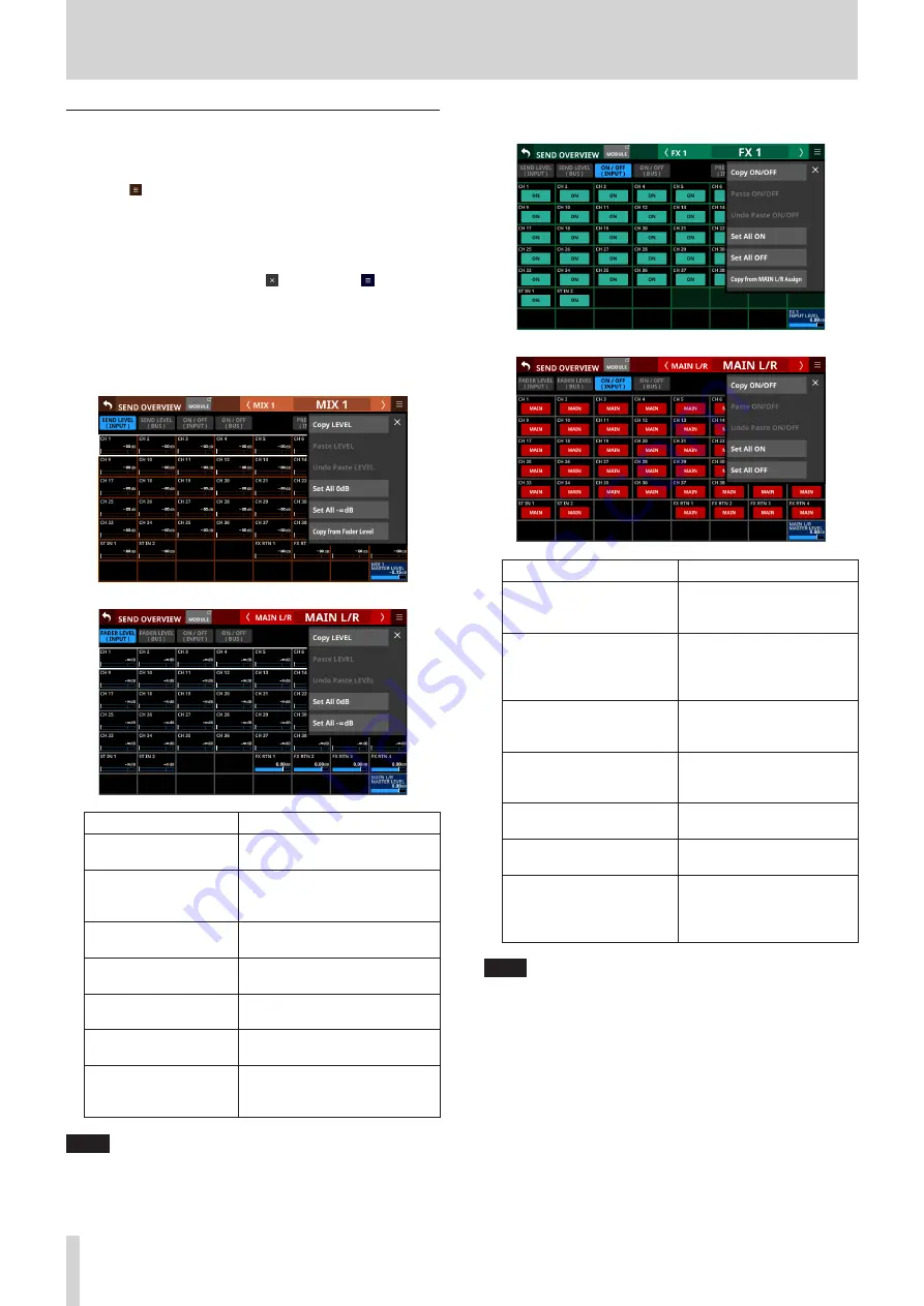
SEND OVERVIEW menu

SEND OVERVIEW menu operations


o

Tap the   button at the top right of the SEND OVERVIEW 

screen to open the SEND OVERVIEW menu for the selected 

bus.


o

Tap menu items to change parameter settings for the 

selected bus all at once.


o

Tap the SEND OVERVIEW menu   button or the  button to 

close the menu.

SEND OVERVIEW menu items

SEND LEVEL (INPUT), SEND LEVEL (BUS) and FADER 

LEVEL (INPUT)

Menu item

Function

Copy LEVEL

This copies the SEND level to the 

selected bus to a buffer.

Paste LEVEL

This pastes the SEND level 

copied to the buffer to the 

selected bus.

Undo Paste LEVEL

This undoes pasting the SEND 

level.

Redo Paste LEVEL

This redoes pasting the SEND 

level.

Set All 0dB

This sets all the SEND levels to 

the selected bus to 0 dB.

Set All −∞dB

This sets all the SEND levels to 

the selected bus to −∞ dB.

Copy from Fader Level

This copies the FADER level to 

the SEND level to the selected 

bus.

NOTE


i

When the selected bus is MAIN L/R, this will change the 

FADER level setting.


i

When the selected bus is MAIN L/R, the “Copy from Fader 

Level” menu item will not be shown.

ON/OFF (INPUT) and ON/OFF (BUS)

Menu item

Function

Copy ON/OFF

This copies the assignment 

settings of the selected bus 

to a buffer.

Paste ON/OFF

This pastes the assignment 

settings to the selected bus 

that were copied to the 

buffer to the selected bus.

Undo Paste ON/OFF

This undoes the pasting of 

assignment settings to the 

selected bus.

Redo Paste ON/OFF

This redoes pasting of 

assignment settings to the 

selected bus.

Set All ON

This turns on all assignment 

settings to the selected bus.

Set All OFF

This turns off all assignment 

settings to the selected bus.

Copy from MAIN L/R Assign

This copies the MAIN L/R 

bus assignment settings to 

the selected bus assignment 

settings.

NOTE


i

When the selected bus is MAIN L/R, this will change the states 

of assignments to the MAIN L/R bus.


i

When the selected bus is MAIN L/R, the “Copy from MAIN L/R 

Assign” menu item will not be shown.

118

  TASCAM  Sonicview 16/Sonicview 24

Summary of Contents for Sonicview 16

Page 1: ...D01407220A Sonicview 16 Sonicview 24 Digital Mixer REFERENCE MANUAL...

Page 2: ...SOURCE ASSIGN screen 51 Making talkback and built in oscillator settings 52 Dante SETUP screen 54 Dante Settings page 54 Notes about Dante 55 Connecting to a Dante network 55 Using Dante Controller 56...

Page 3: ...LICENSE Screen 147 Sonicview 16 24 Error Screen SYSTEM error alert message list 148 Media Manage Screen 150 Formatting media 150 Version Information Screen 151 Firmware update procedures 152 10 Recor...

Page 4: ...LEDs these also support display of input level meters and gain reduction meters o Stereo recording SD cards and stereo playback SD cards and USB flash drives o Word in out thru o 1000BASE T Gigabit E...

Page 5: ...ures Each 8 channel module has a touchscreen with 8 LCD knobs enabling intuitive operation of various parameters for each channel while simultaneously monitoring and checking them Channel screens i Mo...

Page 6: ...TE i Parameter adjustment with LCD knobs i Turning an LCD knob without pressing it will change the parameter value by one step with each click This enables precise parameter adjustment i When adjustin...

Page 7: ...SSER gain reduction meter d COMP DUCKER gain reduction meter e Module icon f Fader level value g Module meter shows signal level of set metering point See MODULE NAME screen on page 122 for details ab...

Page 8: ...g is on because of DCA NOTE The MONITOR SETUP screen MONITOR SOLO page which is where various solo settings can be made can be opened by pressing this key while pressing the MENU key See Making monito...

Page 9: ...and use it to enter names for example By default the unit is set to use a Japanese keyboard Since English and Japanese keyboards use different layouts change the setting on the PREFERENCES screen if...

Page 10: ...m 1 4 stereo phone jack to connect stereo headphones xHeadphone volume Use this to adjust the headphone output level VCAUTION Before connecting headphones minimize the volume with the headphone knob F...

Page 11: ...odule on the Dante SETUP Screen See Dante SETUP screen on page 54 Expansion card slots SLOT 1 SLOT 2 These slots can be used to install expansion cards sold separately Make SLOT settings on the SLOT S...

Page 12: ...ning the unit off See Saving the current settings on page 63 QAC IN connector Plug the included power cord in here GPIO connector overview The GPIO connector on the back of the unit is a parallel cont...

Page 13: ...n the touchscreen When LCD knobs can be used the corresponding indicators light LCD knob Explanation Turn without pressing This allows precise adjustment of one step per click Turn while pressing This...

Page 14: ...phase settings will be shown separately left and right Normal Reversed d This shows the 20dB pad setting status when the input source of the selected module is ANALOG or SB 16D connected by built in...

Page 15: ...odule name for the MIX 1 22 or FX RTN 1 4 module If the name has not been defined the module name will be shown as 1 or FX 1 for example b This shows the PRE POST setting used for MIX 1 22 and FX 1 4...

Page 16: ...lance of the sent signals o Tap this area while pressing the HOME key to set the tapped pan balance setting to center C See 12 List of shortcut operations on page 168 o When the selection frame is sho...

Page 17: ...ill show 2 analog gain knobs and the input level values of the unit or SB 16D MIC LINE input jacks o Tap this area to show the selection frame When the selection frame is shown corresponding LCD knobs...

Page 18: ...the FX RTN module o Tap a SEND level to show the selection frame When the selection frame is shown corresponding LCD knobs can be used to adjust the SEND level shown o Tap the SEND level while pressi...

Page 19: ...rs show the assigned Mute Group numbers Yellow numbers show the assigned DCA numbers See Mute Group Assign page on page 121 and MODULE OVERVIEW Screen on page 78 for changing Mute Group assignments Se...

Page 20: ...green This will be gray when not assigned d Purple rounded buttons are shown when GROUP mode MIX 1 22 buses are ON These appear but cannot be turned on off on the Home Screen b c and d are not shown...

Page 21: ...sent signals o Tap this area while pressing the HOME key to set the tapped pan balance setting to center C See 12 List of shortcut operations on page 168 o When the selection frame is shown tap this...

Page 22: ...te Group numbers Yellow numbers show the assigned DCA numbers See Mute Group Assign page on page 121 for changing Mute Group assignments See DCA Assign page on page 120 for changing DCA assignments o...

Page 23: ...rea This shows submenu items If the submenu has 9 or more items swipe the submenu area up and down to scroll it Tap a submenu item to open a settings screen 4 button Tap this button to close the Menu...

Page 24: ...an link settings page 36 Front Panel Setup User Key Setup Assign functions to the 18 USER KEYS page 43 Layer Master Fader Setup Make the following settings i Assign channel sets and custom layers to t...

Page 25: ...operation mode and speed i Brightness of various displays i Contrast of channel screens page 30 Media Manage Display and format media data page 150 All System Data Save load back up and restore data f...

Page 26: ...ot wear connected headphones when turning the unit on and off Loud noises could damage the speakers or harm your hearing Before turning the power on 1 Minimize output faders along with monitor out and...

Page 27: ...es See Firmware update procedures on page 152 i When an SD card or USB flash drive is being accessed with the BROWSE screen NOTE i Insert an SD card into the SD card slot on the top of the unit so tha...

Page 28: ...ter clock that is 48 kHz 3Clock Master buttons These set the master clock used by this unit for audio synchronization default INT o A 4 mark appears on the master clock being used o If the selected ma...

Page 29: ...the WORD IN connector Dante Synchronize with the clock of a connected Dante system SLOT1 Synchronize with the digital signal clock received through SLOT 1 SLOT2 Synchronize with the digital signal clo...

Page 30: ...o Digital Reference Level setting o Analog Reference Level setting o Cooling fan operation mode and speed settings o Cooling fan operation status display o Temperature value and status display for va...

Page 31: ...nel screens and brightness of the various displays Tap at the top right of the SHORTCUT HELP OPERATION window or the Close Help button to close it 7LCD brightness knob Turn LCD knob 5 lit blue to adju...

Page 32: ...EY footswitch or the GPIO IN See USER DEFINED CONTROLS screen on page 38 1 button Tap this button to return to the Menu Screen NOTE If the button 6 on this screen appears highlighted tapping this butt...

Page 33: ...r area 9 o Tap one of these buttons to switch to showing the corresponding level meters 9Meter Area o The level meters are shown for the page with the highlighted selection button Page name Contents A...

Page 34: ...the metering points for each module type on this page Tap icons to set metering points When a metering point is selected that icon will appear highlighted Module type default CH 1 40 module PRE HPF S...

Page 35: ...locked items will be prohibited i Attempts to operate or control when set to LOCK will cause a message to appear on all touchscreens for about two seconds Lockable controls and operations i LCD touchs...

Page 36: ...stereo link setting on and off default for the CH 1 40 modules When the stereo link is on the button will appear highlighted 4Scroll knob and scrollbar Drag the scrollbar left and right to show CH 1 4...

Page 37: ...e number of modules set to AUX in the BUS MODE area o ST shows the number of AUX mode module pairs that have the stereo link setting on o MONO shows the number of AUX mode modules that have the stereo...

Page 38: ...se to tap the tempo to input the DELAY TIME when the selected effect type is DELAY See MODULE FX Screen on page 90 When the effect type is any delay other than DELAY LCR set Parameter 2 to Delay 1 Whe...

Page 39: ...tion to make the Snapshot number target for STORE RECALL one after that shown at the top of the MENU Screen subject to RECALL Prev Press simultaneously with a key assigned to a Target Key function to...

Page 40: ...light when this setting is on NOTE i Foot Switch GPIO IN i Whe n Mute Group Talkback Monitor Control and SEND ON OFF functions are assigned the selected function will be activated while a Low level s...

Page 41: ...and MUTE changes from on to off Fader Stop CH 1 40 ST IN 1 2 FX RTN 1 4 MIX 1 22 MAIN L R A pulse signal will be output when the status of the specified module becomes as follows Active Low 150ms pul...

Page 42: ...ap these buttons to open a color palette window Tap a color in the color palette to close the window and change the control name display color 4Set function names o The show the names of functions tha...

Page 43: ...his button to apply setting changes and return to the top USER DEFINED CONTROLS Screen wScroll knob icon This icon shows that LCD knob 8 lit light blue can be used to scroll User Key page On this page...

Page 44: ...changed according to the polarity of the footswitch being used 1 Tap the button on the USER DEFINED CONTROLS Screen to open a settings window 2 Tap the Foot Switch Polarity slider in the window to se...

Page 45: ...TIN2 Fader Start Level setting This sets the trigger level of the fader start stop function default 60 dB 1 Tap the button on the USER DEFINED CONTROLS Screen to open a settings window 2 Tap the setti...

Page 46: ...dow Tap a color in the color palette to change the layer key name button color and close the palette window 3Layer Key settings o This shows channel sets and custom layers assigned to LAYER KEY 1 7 o...

Page 47: ...icon shows that LCD knob 8 lit light blue can be used to scroll Default settings for LAYER KEY 1 7 The factory default settings are as follows Sonicview 16 Key Lit color Assigned function LAYER 1 Blue...

Page 48: ...n COPY LAYER This copies the setting state of the selected custom layer to a buffer PASTE LAYER This pastes the custom layer setting state copied to the buffer to the selected custom layer CLEAR LAYER...

Page 49: ...to confirm setting changes Tap the CANCEL button to cancel setting changes Selecting the module button followed by the custom layer slot button 1 Tap the button for the module to be assigned Selecting...

Page 50: ...hted 4Monitor MUTE button Tap this button to turn monitoring signal muting on and off default When this is on the button will appear highlighted NOTE i Output from the headphone jacks will not be mute...

Page 51: ...SOURCE ASSIGN screen On this screen assign monitoring sources for monitoring from the front panel headphone jacks and the rear panel MONITOR OUT L R jacks to the 6 MONITOR SELECT buttons To open this...

Page 52: ...ON and OFF Touch this button continuously to turn the function on only while being touched i Using the User Defined Control function TALKBACK ON OFF switching is also possible with a USER KEY the foo...

Page 53: ...ptions SINE WAVE default PINK NOISE WHITE NOISE Tap an option button to close the menu and show the selected signal type wFREQ This appears if the signal type is set to SINE WAVE Use this to adjust th...

Page 54: ...IP address setting mode Tap this area to open a window where AUTO DHCP or STATIC can be selected Item Content IP Address If the Addressing item is set to AUTO this will show the assigned IP address If...

Page 55: ...unit you must also set up the Ethernet network that it is connected to a computer that runs Dante Controller and other devices that support Dante Dante controller is not necessary for use however whe...

Page 56: ...it depth of each Dante device NOTE Settings made using Dante Controller are stored in the built in memory of each Dante device Unless settings are modified connections will not change even if Dante Co...

Page 57: ...m the transmitting device to the receiving device passes through 10 gigabit switching hub 2msec The transmission speed of the transmitting device is 100 Mbps 5msec Use this maximum selectable latency...

Page 58: ...erating normally Precautions when using an IF DA64 The Dante module built into this unit an IF DA64 Dante card installed in a SLOT and the unit s master clock must be synchronized Do this as follows o...

Page 59: ...For this reason a 48K Frame MADI input signal that does not match the sampling frequency of the receiving device cannot be received as proper audio data When using a 48K Frame MADI signal always matc...

Page 60: ...IC default 0 0 0 0 o This will be gray when IP SETUP is AUTO o Tap the address fields to open the IP Address Subnet Mask and Default Gateway screens IP ADDRESS setting screen See IP Address Subnet Mas...

Page 61: ...machine name Sonicview 16 Sonicview16 Sonicview 24 Sonicview24 The combination of characters input can be changed depending on the status of the Caps lock and Shift keyboard buttons on the Machine na...

Page 62: ...tton to confirm the input and return to the Network Setup Screen Changed settings will be reflected in the IP Address Subnet Mask and Default Gateway fields of the Network Setup Screen NOTE i Each inp...

Page 63: ...ngs data settings have already been output to the memory so these operations are not necessary before turning the power off 1 Press the MENU key to open the Menu Screen 2 On the Menu Screen show the S...

Page 64: ...n frame is shown to open this screen CH 1 40 modules ST IN 1 2 modules 1LOCK UNLOCK button o This button locks unlocks routing setting change operations for the unit This is always locked at the time...

Page 65: ...When the LOCK UNLOCK button 1 is set to UNLOCK tap this button to turn internal oscillator signal input on or off default o When turned on the input for the selected module will switch to the signal f...

Page 66: ...set to LOCK the BATCH SETUP button is disabled i If routing operation is set to LOCK on another touchscreen while a multiple setting window is open it will close automatically Direct out signal outpu...

Page 67: ...iple output ports will appear to the bottom right of the button o Tap this button to open the INSERT SEND PORT SELECT Screen where INSERT SEND signal output ports can be selected See INSERT SEND PORT...

Page 68: ...top of the Home Screen of a MIX 1 22 or MAIN L R Master module to open this screen MIX 1 22 modules MAIN L R Master module 1LOCK UNLOCK button o This button locks unlocks routing setting change operat...

Page 69: ...on the Others button o When the LOCK UNLOCK button 1 is set to UNLOCK tap the Others button to open the OUTPUT PORT SELECT Screen where output ports not shown on the MODULE OUTPUT Screen can be select...

Page 70: ...This will return to the MODULE OUTPUT Screen where the OUTPUT PORT selection button will show the selected output port NOTE i When the LOCK UNLOCK button is set to LOCK the BATCH SETUP button is disab...

Page 71: ...sources The selected button will be highlighted Buttons that cannot be used will appear dark gray If a button that cannot be used is selected it will appear dark blue 4Scroll knob and scrollbar These...

Page 72: ...OUT Select USB audio interface output ports 3Output port selection buttons o When the LOCK UNLOCK button 1 is set to UNLOCK tap these buttons to select output ports The selected button will be highli...

Page 73: ...a page name to switch to the page with the corresponding output port group The name of the selected page will be highlighted An will appear next to the name of the page that the selected output port...

Page 74: ...group page switches o These show input source group page names o Tap a page name to switch to the page with the corresponding input source group The name of the selected page will be highlighted An w...

Page 75: ...t is on Page name Contents ANALOG OUTPUT Select analog output ports Dante Select built in Dante output ports SLOT 1 Select the output ports of the expansion card installed in SLOT 1 SLOT 2 Select the...

Page 76: ...f on one screen will reopen the Home Screen on the other touchscreens 3 buttons Tap these buttons to move left and right in order on the layer between modules to show and activate different ones for o...

Page 77: ...dynamics effect settings for the selected module SEND Make bus send settings for the selected module PAN Make pan settings for the selected module OUTPUT Make output settings for the selected module N...

Page 78: ...OINT page of the METER SETUP Screen See METERING POINT page on page 34 2Level meters This shows the level of the signal at the set metering point 3MUTE GROUP button Tap this button to open the DCA Mut...

Page 79: ...N 38 57 37 When Analog Reference Level 4 dBu Status before switching pad setting Analog GAIN after switching pad setting Analog GAIN 12 46 Same value PAD ON Analog GAIN 8 11 12 PAD OFF Analog GAIN 47...

Page 80: ...the HPF on off Default OFF When this is ON the button will appear highlighted pHPF frequency This adjusts the cutoff frequency of the HPF Range 20 Hz 1 0 kHz default 79 Hz Turn LCD knob 3 4 5 lit blu...

Page 81: ...this button to open the MODULE SEND PAN Screen for the selected module See MODULE SEND PAN Screen on page 102 lMIX FX SEND levels o This list shows the on off and PRE POST states and the send levels t...

Page 82: ...SAFE page on page 134 8Metering Point position indicator The highlighted indicator shows the position of the set metering point 9INPUT button o This shows the input source name o Tap this button to o...

Page 83: ...Normal Reversed rD TRIM knob Use this to adjust the digital trim value Range 50 0 dB 20 0 dB default 0 0 dB Turn LCD knob 3 lit red to adjust it tMUTE button Tap this button to turn muting on off for...

Page 84: ...een See MODULE SAFE page on page 134 9Metering Point position indicator The highlighted indicator shows the position of the set metering point 0FX Processing button Tap this button to open the MODULE...

Page 85: ...e 34 i When the Metering Point is OUTPUT and the corresponding bus has not been assigned to an output port not being output from the unit meters will not be shown 2Level meters This shows the level of...

Page 86: ...sed to set this yFADER LEVEL Use this to adjust the FADER level of the selected module signal Range dB 10 0 dB default 0 0 dB Turn LCD knob 5 lit blue to adjust it NOTE i The channel faders on top of...

Page 87: ...3LOCK UNLOCK button o This button locks unlocks routing setting change operations for the unit This is always locked at the time of start up o When set to LOCK tapping INPUT SOURCE 1 and OSC 3 buttons...

Page 88: ...n as 0 8PAD button o This shows the PAD button when the input source of the selected module is ANALOG or SB 16D connected by built in Dante o Tap this button to turn the 20dB pad on off Default off Wh...

Page 89: ...the 48V button to turn phantom power 48V on off Default OFF When phantom power is on the button will be highlighted tBATCH SETUP button When the LOCK UNLOCK button 3 is set to UNLOCK tap this button t...

Page 90: ...n to open a setting confirmation window 5 Tap the OK button to set multiple digital trim values at the same time This will return to the MODULE INPUT Screen MODULE FX Screen Make effect settings on th...

Page 91: ...ELAY TIME intervals If a DELAY TIME is 200 msec or less the indicator will stay highlighted NOTE Using the User Defined Control function tap tempo input can also be operated with USER KEY FOOTSWITCH a...

Page 92: ...0 HI DAMP 500 Hz 16 0 kHz 3 36 kHz STEREO DELAY Parameter name Range default DELAY TIME 1 msec 1500 msec 100 msec FEEDBACK 0 100 20 HI DAMP 500 Hz 16 0 kHz 3 36 kHz PING PONG DELAY Parameter name Ran...

Page 93: ...name Range default RATE 0 05 Hz 10 00 Hz 0 20 Hz DEPTH 0 100 10 DELAY TIME 0 msec 100 msec 40 msec PHASE 0 deg 180 deg 180 deg PHASER Parameter name Range default RATE 0 05 Hz 10 0 Hz 0 40 Hz STAGE 4...

Page 94: ...meter This shows the signal level output from the GATE EXPANDER DE ESSER 5GATE EXPANDER DE ESSER ON OFF button o Tap this button to turn the dynamics effect on off Default OFF o When on this button t...

Page 95: ...0 dB 40 dB RATIO 1 1 2 1 4 1 8 1 16 1 32 1 64 1 4 1 KNEE HARD MID SOFT MID ATTACK 0 ms 125 ms 10 ms RELEASE 5 ms 5 00 s 250 ms DE ESSER Parameter name Range default THRESHOLD 40 dB 0 dB 15 dB KNEE HAR...

Page 96: ...he HPF EQ frequency response graph and the EQ parameters will appear highlighted NOTE HPF is only shown for CH 1 40 modules 3HPF EQ frequency response graph o This shows graphs of the HPF and EQ frequ...

Page 97: ...se the corresponding LCD knobs to adjust the values Parameter name Range default G 18 0 dB 18 0 dB 0 dB F 20 Hz 20 0 kHz 297 Hz Q 0 10 17 31 1 04 NOTE Tap the EQ gain area while pressing the HOME key...

Page 98: ...hscreen separately Default ON When this is on the button becomes highlighted and audio signal frequency response meters for the POST FADER position are shown behind the GEQ overall setting graph 4 and...

Page 99: ...shows the amount of gain reduction from the COMP DUCKER 5OUTPUT level meter s This shows the level s of the signal s output from the COMP DUCKER 6COMP DUCKER ON OFF button Tap this button to turn the...

Page 100: ...DUCKER Dynamics parameters NOTE Use the corresponding LCD knobs and buttons to change the settings They can also be adjusted by dragging the green and blue and icons on the graph COMP Parameter name R...

Page 101: ...P or MODULE DUCKER Screen to open this screen The COMP DUCKER KEY IN source can be selected with the following buttons i SELF default i CH 1 40 i MIX 1 22 i MAIN L R The selected button will be highli...

Page 102: ...can also be made for CH 1 40 modules when Stereo Link is on and for ST IN 1 2 and FX RTN 1 4 modules o MODE o IMAGE Tap the following areas for each module on the Home Screen to open this screen o SE...

Page 103: ...status will be shown in the bus area of the lower number and the level and button will be shown in the bus area of the higher number i SEND PAN parameters for buses with the PAN LINK setting on appea...

Page 104: ...N L R bus on off When this is on the button will appear highlighted and the signal will be sent to MAIN L R bus Module name default CH 1 40 On ST IN 1 2 On FX RTN 1 4 On MIX 1 22 Off NOTE i A list of...

Page 105: ...a ST IN 1 2 or FX RTN 1 4 module 8BAL indicator shown for stereo modules only This adjusts the balance of the signals sent to the MAIN L R bus Range L100 C R100 default C When the selection frame is s...

Page 106: ...will close the message without changing the setting o If the selected output port is not shown on one of the main buttons the output port name will be shown on the Others button o Tap the Others butto...

Page 107: ...time on page 69 Change settings for multiple designated channels at the same time 716ch BLOCK button MIX 1 16 modules only When the LOCK UNLOCK button 3 is set to UNLOCK tap this button to open a win...

Page 108: ...ry Tap this area to open the LIBRARY Screen for the selected module NOTE i The underlined words in the menu item list will be replaced with the MODULE screen names of the selected module i The menu it...

Page 109: ...6 Modules TASCAM Sonicview 16 Sonicview 24 109...

Page 110: ...llowing USER KEYS by default on the User Key page i USER KEY 5 12 Sends On Fader Mix1 8 SENDS ON FADER screen Select the buses subject to SENDS ON FADER operation on this screen Press the SENDS ON FAD...

Page 111: ...t the SEND OVERVIEW Screen shows a list of the SEND parameters a aligned horizontally on the analog mixer and can be used to operate them MIX 1 22 bus SEND OVERVIEW Screen Tap Menu Screen Mixer Setup...

Page 112: ...s button to open the SEND OVERVIEW menu for the selected MIX 1 22 bus Tap menu items to change parameter settings for the selected MIX 1 22 buses See SEND OVERVIEW menu on page 118 6Page selection but...

Page 113: ...X 1 22 buses Default OFF When ON buttons will be highlighted NOTE An assignment button for the same bus as the selected bus shown in the module name area 4 is not shown wPRE POST buttons o This shows...

Page 114: ...e PRE POST INPUT page SEND PAN INPUT page SEND PAN BUS page NOTE Tap a level while pressing the HOME key on the top panel to set that level to 0 dB 1 button Tap this button to return to the screen sho...

Page 115: ...bs lit green to adjust SEND levels Range dB 10 dB default dB 8FX INPUT LEVEL This adjust the input level for the FX 1 4 module that corresponds to the FX 1 4 bus shown Range dB 10 dB default 0 0 dB Wh...

Page 116: ...top of the MODULE Screen for the MAIN L R Master module can also be tapped to open this screen FADER LEVEL INPUT page FADER LEVEL BUS page ON OFF INPUT page ON OFF BUS page SEND PAN INPUT page SEND PA...

Page 117: ...onding LCD knobs lit blue to adjust FADER levels Module name Range default CH 1 40 dB 10 dB dB ST IN 1 2 FX RTN 1 4 0 0 dB 8MAIN L R MASTER LEVEL This adjusts the FADER level of the MAIN L R Master mo...

Page 118: ...level to the selected bus NOTE i When the selected bus is MAIN L R this will change the FADER level setting i When the selected bus is MAIN L R the Copy from Fader Level menu item will not be shown O...

Page 119: ...ed bus to POST SEND PAN INPUT and SEND PAN BUS Menu item Function Copy PAN BAL This copies the pan balance settings to the selected bus to a buffer Paste PAN BAL This pastes the pan balance settings t...

Page 120: ...et to ON for the DCA module SOLO will stay ON for that module when the DCA module SOLO is set to OFF o The SOLO indicators will blink for modules that have SOLO turned on in DCA modules o DCAs are ope...

Page 121: ...ot Recall Safe function for the selected Mute Group Default off When this is on the button will appear highlighted 3Module type selection pages These are page buttons for module types assigned to the...

Page 122: ...d as part of a mute group NOTE Using the User Defined Control function the Mute Group function can also be operated with USER KEYS FOOTSWITCH and GPIO IN controls See USER DEFINED CONTROLS screen on p...

Page 123: ...shown in the keyboard input area to the copy buffer o Tap the Paste button to paste the characters in the copy buffer to the keyboard input area Setting and editing user module names User module name...

Page 124: ...he abbreviated name Changing the keyboard keys The Caps lock and Shift button settings change the selection of characters that can be input as shown below NOTE The Shift button automatically deactivat...

Page 125: ...module color setting This will change the module name background color shown on screens as well as the lit color of channel color bars NOTE Tapping the keyboard input area on a NAME screen will reopen...

Page 126: ...ed For example routings can be kept the same when recalling snapshots Using snapshot functions at the top of the Menu Screen Snapshot functions can be conducted using the snapshot function area on the...

Page 127: ...f the current snapshot will be stored in it i If the save destination data slot is not empty and the CONFIRMATION settings window STORE setting is ON a save confirmation message will be shown i Tappin...

Page 128: ...l be USER KEY data slot number Recalling snapshots Follow one of the procedures below to recall load snapshot data Using RECALL at the top of the Menu Screen 1 Tap the buttons to open the snapshot num...

Page 129: ...cview 16 data on a Sonicview 24 1 Analog input 17 24 settings M L 17 24 Input Assign Not imported No assignment M L 17 24 Phantom ON OFF Not imported Set to OFF M L 17 24 PAD ON OFF Not imported Set t...

Page 130: ...utton on the Menu Screen 6RECALL button This has the same function as the RECALL button on the Menu Screen 7 icon This has the same function as the icon on the Menu Screen 8 icon Tap this icon to clos...

Page 131: ...editing menu button o This button only appears for the selected data slot o Tap this button to open a menu for editing the selected data slot See Library menu on page 132 for details iRECALL UNDO RED...

Page 132: ...op panel USB port can also be used to input and edit characters 2Copy button Tap this button to copy the settings data of the selected snapshot NOTE The LIBRARY Screen for snapshots is the only one th...

Page 133: ...to paste and return to the Snapshot List Screen NOTE i When snapshot setting data is saved in the paste destination a confirmation message will be shown i Tap the CANCEL button to close the confirmat...

Page 134: ...check marks 4 and be highlighted light blue NOTE i Settings included in INPUT OSC PARAMETERS Analog Gain Analog Gain GANG On Off PAD On Off Phantom On Off Phase D Trim HPF Freq HPF On Off CH OSC INPU...

Page 135: ...utton will be highlighted when switched to export mode o Tap the left arrow button to switch the screen to import mode The button will be highlighted when switched to import mode NOTE The unit will be...

Page 136: ...a will be added to the exported data list 6 and an export complete message will appear at the top of the screen NOTE i A confirmation message will be shown if snapshot data with the same name already...

Page 137: ...n data slot The import destination data slot and the IMPORT button will appear highlighted 8 Tap the IMPORT button The imported snapshot data will be added to the snapshot list 3 NOTE i An OVERWRITE c...

Page 138: ...e parameters included in module libraries are the same as the parameters used for Copy MODULE See MODULE menu on page 108 LIBRARY screen overview Use various library functions and manage and edit libr...

Page 139: ...g data name the following message will be shown Default name already exists change name CANCEL RENAME i A confirmation message will be shown if the selected data slot has settings data i Tap the Cance...

Page 140: ...selected All System Data file from the internal storage and close the confirmation message The selected All System Data file will be removed from the list of saved files 1 3SAVE button Tap this button...

Page 141: ...plying it to the mixer 1 Tap the LOAD button 4 when an All System Data file is selected to open a confirmation message to load that data NOTE To load network settings tap the include NETWORK Settings...

Page 142: ...ith the same name already exists on the backup media i Tap the CANCEL button to close the confirmation message i Tap the OVERWRITE button to overwrite the All System Data file with the same name and c...

Page 143: ...If either an SD card or a USB flash drive is connected but not both the media selection menu will not be shown 4 Select the file to restore and tap the RESTORE button A confirmation message will appe...

Page 144: ...the USB flash drive and SD card states o Tap this area to open the MEDIA MANAGE Screen See Media Manage Screen on page 150 4RECORDER PLAYER o This shows the operation status of the internal recorder...

Page 145: ...kground color becomes gray This includes device temperature errors and other errors that are resolved automatically as well as system clock errors and other errors that are resolved manually 3 buttons...

Page 146: ...s the order that it occurred o Tap this area to open the screen that corresponds to the content of the error alert 4Blinking error bar Until errors and alerts are resolved a blinking red line will be...

Page 147: ...icenses for open source software used by this unit o Tap the b icon to show the license document for that open source software o When a license document is open tap the 5 icon to close it 2Scrollbar d...

Page 148: ...SLOT slot number card name failure Trouble was detected with the expansion card Internal Dante Error Dante Module Unavailable The built in Dante module is in an unusable state in safe mode updating Da...

Page 149: ...the power was off Internal Dante Alert Dante I O Sample rate changed by Dante Controller The internal Dante input output sampling frequency was changed by Dante Controller Storage Media Alert Unrecogn...

Page 150: ...card is write protected it cannot be formatted Disable write protection See SD card write protection switches on page 27 i Formatting erases all the data on the SD card or USB flash drive Confirm that...

Page 151: ...this screen information is shown about the system firmware versions and build numbers as well as cards installed in SLOT 1 and SLOT 2 Tap Menu Screen System Setup Version Information to open the Vers...

Page 152: ...f there are more files than can be shown on the display at once swipe the list up or down to scroll it i The screen shown above is an example The actual appearance will differ 6 Tap the firmware to us...

Page 153: ...is shown in V1 0 2 and earlier versions Even if a RESTART button appears do not tap it Always use the POWER switch to restart the unit 11 After the unit restarts confirm that the latest firmware is be...

Page 154: ...es the bar extends from the left to the right 6RECORDER information area When recording the background of this area becomes light red to show clearly that recording is in process 7Tape reel icon When...

Page 155: ...ECT Screen MIX 1 22 and MAIN L R signals can be selected as inputs to the left and right channels of the recorder default MAIN L R PLAYER Section 1Playback transport status This icon shows the transpo...

Page 156: ...green m When playing back or in playback standby touch this button continuously to search forward backward while outputting sound Tap this when the player is stopped to skip to the previous next file...

Page 157: ...SSIGN Screen 1Page selection buttons o These show the names of the input modules to which the player outputs are assigned No assign is shown when no player output is assigned o Tap these buttons to sw...

Page 158: ...n for recording folder selection Tap the recording folder name in the RECORDER Section to open the BROWSE screen where the recording destination folder can be selected Move to the desired existing fol...

Page 159: ...ed can be input The combination of characters input can be changed depending on the status of the Caps lock and Shift keyboard buttons on the Make Folder Screen See Changing the keyboard keys on page...

Page 160: ...rScrollbar This appears when the number of folders and files exceeds the amount that can be shown on the display at the same time Drag the scrollbar to scroll the screen The file list can also be scr...

Page 161: ...oard buttons on the Make Folder Screen See Changing the keyboard keys on page 124 for details about changing the keyboard 7Level change button Tap the button to show the folder level one step above th...

Page 162: ...the folder to the left of the button i This operation is not possible during recording and playback y buttons o Tap one of these buttons to select an audio file make it subject to playback and start...

Page 163: ...FOLDER button 9 This sets it as the recording folder and REC FOLDER appears Setting the playback folder 1 Tap Menu Screen Recorder Player menu Recorder Player to open the RECORDER PLAYER Screen 2 Tap...

Page 164: ...op or another location 3 Double click the TASCAM Sonicview USB exe file in the folder that appears after uncompression to launch the installation software ATTENTION If you open a zip file without deco...

Page 165: ...rding to use conditions Default Normal 256 Samples NOTE On macOS adjust this with application settings Setting Sound Properties 1 Open the Control Panel on the Windows computer NOTE Follow these proce...

Page 166: ...ble Setting procedures for use with OBS Studio and other streaming applications Conduct the procedures in this document before launching the streaming application Windows computer sound settings Set t...

Page 167: ...Format Set the sample rate and bit depth for the Default Device on the Play tab to the same values set on the Record tab 11 Launch the streaming application and proceed with streaming and other functi...

Page 168: ...eens various indicators and the lamp connected to the LAMP connector on the rear panel at the same time Press and turn any LCD knob while pressing the HOME key on the top panel This adjusts the bright...

Page 169: ...turned off use the Save Current Settings item on the Menu Screen to save the current settings in the internal memory before turning the power off Touchscreen operations are not possible o If the syst...

Page 170: ...nicview 24 Tap the RESTART buttons to open a restart confirmation window Tap the RESTART button on the confirmation screen to restart the system and enable proper LCD knob operations Alternatively fol...

Page 171: ...c o ADC 96 kHz 32 bit o DAC 96 kHz 24 bit o Digital I O sampling frequencies 96 kHz 48 kHz Signal Delay 48 kHz ms Routing details A to A 0 510 MIC LINE IN w CH module w MAIN L R BUS w MAIN L R module...

Page 172: ...nicview 24 17 24 Connectors 6 3mm 1 4 TRS phone jacks Tip HOT Ring COLD Sleeve GND Input levels Pad off Maximum input level 12 dBu TRIM at minimum Minimum input level 62 dBu TRIM at maximum Pad on Max...

Page 173: ...D 480 Mbps USB port Rear panel Connector USB Type B Protocol USB 2 0 HIGH SPEED 480 Mbps LAMP jack Connector XLR 4 pin female pin 4 12V pin 3 GND Power supply voltage 0 V 12 V Maximum output 5 W WORD...

Page 174: ...er with ARM64 CPUs Mac Supported operating systems macOS Monterey 12 macOS Big Sur 11 macOS Catalina 10 15 Computer hardware requirements Mac with a USB 2 0 or higher port Other Power AC 100 240V 50 6...

Page 175: ...n Sine Wave or Pink Noise or White Noise Trigger Source ST IN 1 ST IN 1 2 module MAIN L MAIN R SOLO L SOLO R MIX1 MIX22 ADC PEQ 4BAND RTA RTA L RL RL RL R 1 2 3 4 19 20 22 21 MIX1 22 master section SO...

Page 176: ...PAD ON 12 dB 42 dB 55 1 dB click 2 dB click PAD OFF ON Phantom OFF ON OSC INPUT OFF ON Phase Sw Normal Reverse D TRIM 50 0 dB 20 0 dB 141 0 5 dB click 2 0 dB click HPF Switch OFF ON Freq 20 Hz 1 0 kHz...

Page 177: ...0 18 0 361 0 1 dB click 1 0 dB click COMP DUCKER Switch OFF ON Type COMP DUCKER Key In Source SELF CH 1 40 MIX 1 22 MAIN L R Key In Filter Switch OFF ON Key In Filter Type HPF BPF LPF Key In Filter F...

Page 178: ...up 8 Groups Stereo Link OFF ON Output Modules Function Parameter steps Fine Step when LCD knob turned without being pressed Coarse Steps when LCD knob turned while being pressed Insert Switch OFF ON 4...

Page 179: ...ick 5 00 msec click Delay Point INPUT PRE FADER Delay Edit Unit meter feet msec FADER LEVEL dB 120 dB 10 0 dB 1024 1 point click 10 dB 10 dB 0 05 dB click 40 point click 10 dB 10 dB 2 dB click MUTE OF...

Page 180: ...everb spread STEREO REVERB TYPE HALL ROOM 2 1 point click 1 point click Reverb type PRE DELAY 0 msec 200 msec 201 1 msec click 10 msec click Time before reverb starts after sound is input REVERB TIME...

Page 181: ...1 point click 5 point click Feedback amount HI DAMP 500 Hz 16 0 kHz 61 1 point click 3 point click Cutoff frequency of high frequency attenuation STEREO DELAY DELAY TIME 1 msec 1500 msec 1500 1 msec c...

Page 182: ...t FLANGER RATE 0 05 Hz 10 0 Hz 101 1 point click 5 point click Flanger modulation frequency DEPTH 0 100 101 1 click 5 click Flanger depth DELAY TIME 0 msec 100 msec 101 1 msec click 5 msec click Time...

Page 183: ...c P005 GATE Rack Tom 1 Threshold Range Attack Hold Decay 20 dB 40 dB 0 msec 60 msec 380 msec P006 GATE Rack Tom 2 Threshold Range Attack Hold Decay 20 dB 40 dB 0 msec 60 msec 300 msec P007 GATE Snare...

Page 184: ...B P006 Floor Tom Low Low Mid Hi Mid Hi Q 2 02 Q 1 41 Q Q 1 80 Freq 79 Hz Freq 420 Hz Freq Freq 5 04 kHz Gain 3 5 dB Gain 4 0 dB Gain Gain 3 0 dB P007 Hi Hat Low Low Mid Hi Mid Hi Q Q 0 92 Q Q Freq Fre...

Page 185: ...Parameters P001 A Gtr Threshold Ratio Knee Attack Release Output Gain 29 dB 2 50 1 Mid 1 msec 200 msec 2 dB P002 Bass Line Threshold Ratio Knee Attack Release Output Gain 27 dB 3 33 1 Mid 30 msec 230...

Page 186: ...c 2 8 sec 8 00 kHz P006 REVERB Vo Rev 2 TYPE PRE DELAY REVERB TIME SPREAD HALL 40 msec 2 4 sec 70 P007 LCR DLY Delay LCR HI DAMP DELAY TIME L DELAY TIME C DELAY TIME R FEEDBACK WET LEVEL L WET LEVEL C...

Page 187: ...16 Parameter tables TASCAM Sonicview 16 Sonicview 24 187...

Page 188: ...d https www tascam eu en Phone 44 1923 797205 Luminous House 300 South Row Milton Keynes Buckinghamshire MK9 2FR UK TEAC EUROPE GmbH https www tascam en de Phone 49 611 71580 Bahnstrasse 12 65205 Wies...

Reviews: