6 – Modules
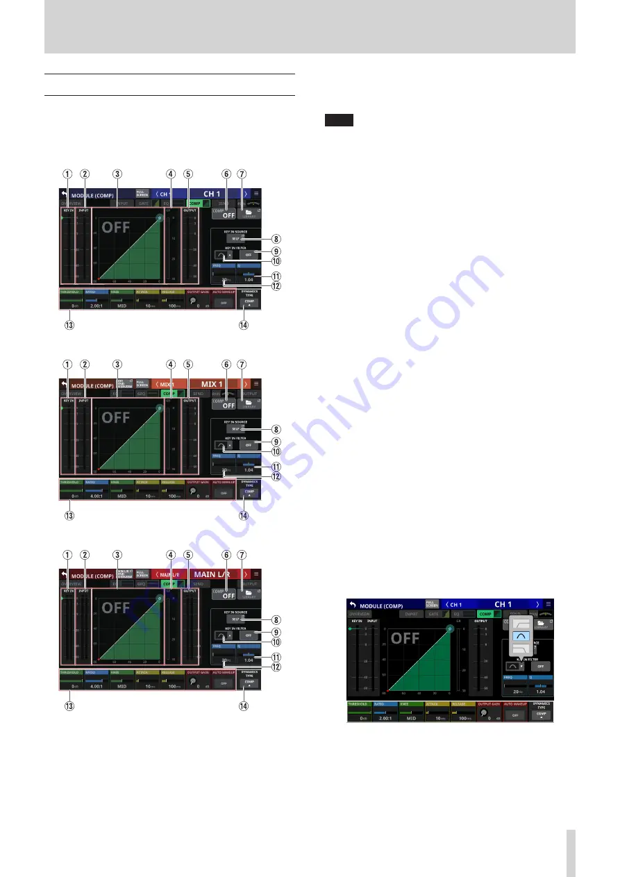
MODULE (COMP/DUCKER) Screen
COMP and DUCKER settings can be made on the MODULE
(COMP) and MODULE (DUCKER) Screens for CH 1–40, MIX 1–22
modules and MAIN L/R Master modules.
Tap the COMP/DUCKER area on the Home Screen to open this
screen.
CH 1–40 modules
MIX 1–22 modules
MAIN L/R Master module
1
KEY IN level meter(s)
This shows the KEY IN SOURCE level input to the COMP/
DUCKER.
NOTE
i
If the module is stereo and the KEY IN SOURCE module is
stereo, a stereo level meter will be shown.
i
If the module is mono and the KEY IN SOURCE module is
stereo, a mono level meter will be shown, and the L+R mono
level will be used as the trigger.
2
INPUT level meter(s)
This shows the signal level(s) of the selected module input to
the COMP/DUCKER.
3
Dynamics input/output characteristics graph
This shows graphs of the COMP/DUCKER input/output
response.
4
Gain reduction meter
This meter shows the amount of gain reduction from the
COMP/DUCKER.
5
OUTPUT level meter(s)
This shows the level(s) of the signal(s) output from the
COMP/DUCKER.
6
COMP/DUCKER ON/OFF button
Tap this button to turn the dynamics effect on/off. (Default:
OFF)
When on, this button, the dynamics input/output response
graph and parameters will appear highlighted.
7
LIBRARY button
Tap this button to open the COMP/DUCKER LIBRARY Screen.
(See “Various LIBRARY Screens” on page 138.)
8
KEY IN SOURCE button
o
This shows the name of the selected KEY IN source.
(Default: SELF)
o
Tap this button to open the KEY IN SOURCE SELECT
Screen. (See “KEY IN SOURCE SELECT screen” on page
9
KEY IN FILTER button
Tap this button to turn KEY IN FILTER on/off. (Default: OFF)
0
KEY IN FILTER TYPE button
o
This shows the KEY IN FILTER type.
o
Tap this button to open the type selection menu.
Options: HPF, BPF (default), LPF
q
Q
This adjusts the Q value when the KEY IN FILTER type is
bandpass.
Range: 0.1 - 17.31 (default: 1.04)
When the selection frame is shown, turn LCD knob 8 (lit light
blue) to adjust it.
TASCAM Sonicview 16/Sonicview 24
99


