5 – Routing
4. Tap the OK button to set multiple input sources at the same
time.
This will return to the MODULE (INPUT) Screen where the
INPUT SOURCE selection button will show the selected
input source.
NOTE
i
When the LOCK/UNLOCK button is set to “LOCK”, the 8ch
BLOCK, 16ch BLOCK and 24ch BLOCK buttons are disabled.
i
If routing operation is set to “LOCK” on another touchscreen
while a multiple setting window is open, it will close
automatically.
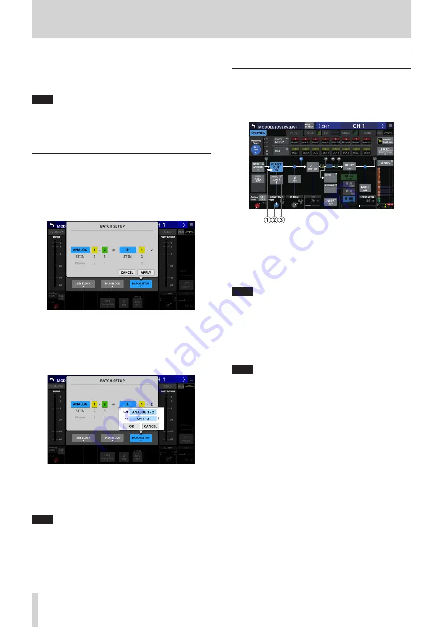
Setting inputs sources for multiple
channels at the same time in batches
1. When the LOCK/UNLOCK button (
1
) is set to “UNLOCK”, tap
the BATCH SETUP button on the MODULE (INPUT) Screen to
open a window where multiple input sources can be set at
the same time.
2. Swipe the options up and down to select the input sources
and the modules they will be assigned to.
Selections can also be changed by turning the LCD Knobs
2–6 with the same colors.
3. Tap the APPLY button to open a setting confirmation
window.
4. Tap the OK button to set multiple input sources at the same
time.
This will return to the MODULE (INPUT) Screen where the
INPUT SOURCE selection button will show the selected
input source.
NOTE
i
When the LOCK/UNLOCK button is set to “LOCK”, the BATCH
SETUP button is disabled.
i
If routing operation is set to “LOCK” on another touchscreen
while a multiple setting window is open, it will close
automatically.
Direct out signal output routing
The CH 1–40 modules have direct out functions.
Set direct out signal output routing on the MODULE (OVERVIEW)
Screen for CH 1–40 modules.
Tap the MODULE NAME area on the Home Screen to open this
screen.
CH 1–40 modules
1
DIRECT OUT button
Tap this button to turn DIRECT OUT ON (default) or OFF.
When ON, the signal will be output directly from this point,
and this button and the DIRECT OUT TRIM knob will be
highlighted.
NOTE
The DIRECT OUT POINT for CH 1–40 modules can also be
changed as explained in “CH 1-40 CONFIG page” on page
2
DIRECT OUT TRIM knob
Use this to adjust the DIRECT OUT output signal level.
Range: -20 dB - +20 dB (default: 0 dB)
Turn LCD knob 2/4/5/7 (lit blue) to adjust it.
NOTE
The knob used for this operation depends on DIRECT OUT
POINT and DELAY POINT settings.
3
OUTPUT button
o
This shows the name of the output port that the DIRECT
OUT signal is assigned to. If it has been assigned to
multiple output ports, “…” will appear to the bottom right
of the button.
o
Tap this button to open the DIRECT OUT PORT SELECT
Screen where DIRECT OUT output ports can be selected.
(See “DIRECT OUT PORT SELECT screen” on page 71.)
66
TASCAM Sonicview 16/Sonicview 24


