2-3. Operation Panel
2-38
2-3-2. Menu
setup
mode
You can set the menu according to your requirements.
To enter menu setup mode, press the
[MENU]
key while “On Line Ready” is displayed on the LCD.
For details, refer to the User’s Manual.
2-3-3. Test
mode
The following Test modes are available:
Operation
Description
[FEED]
+ “Power ON”
Enters self print mode.
[STOP]
+ “Power ON”
Enters hex dump mode.
[MENU]
+ “Power ON”
Enters menu list printing mode.
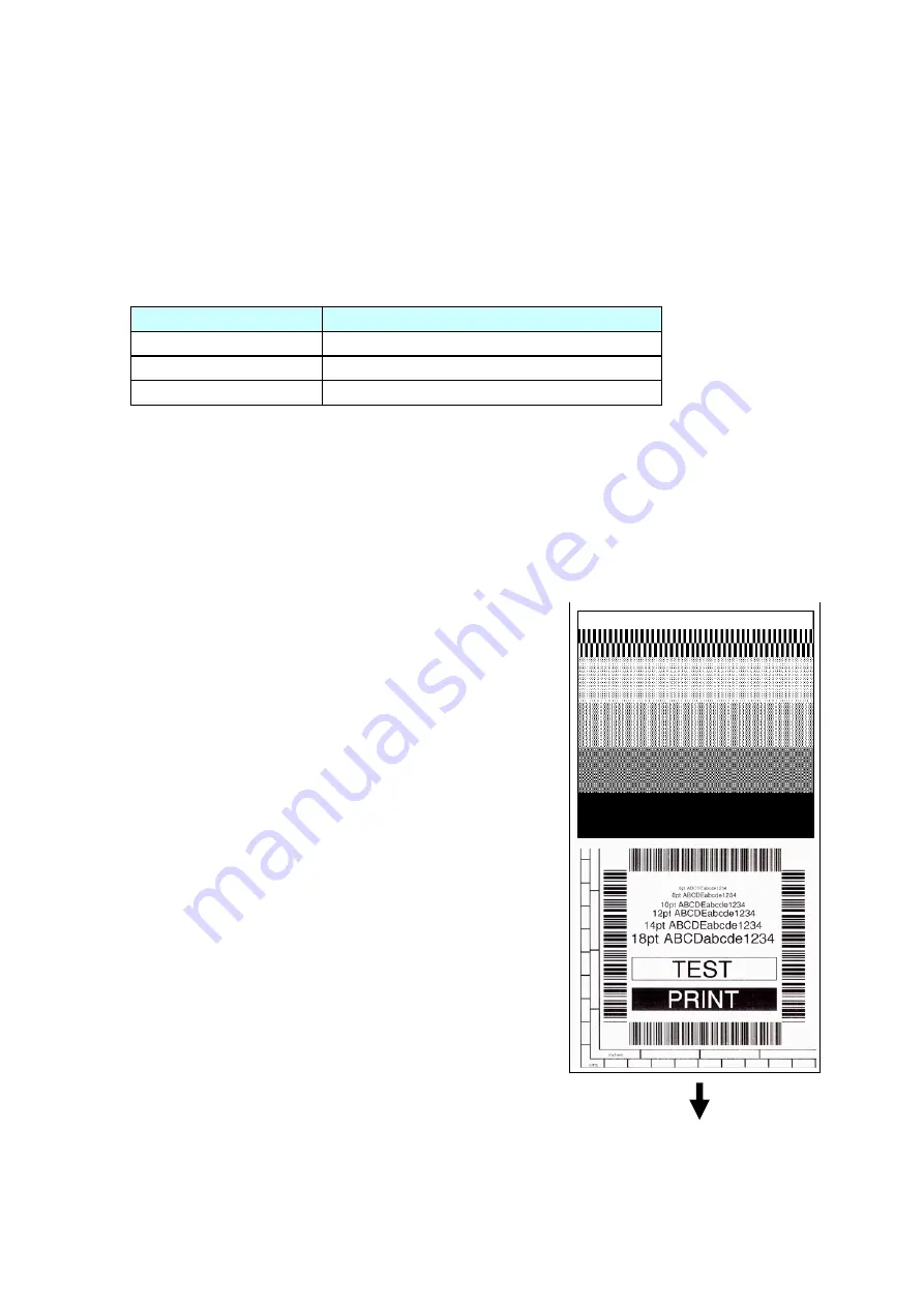
(1) Self print mode
You can check the printing quality by printing the built-in self print pattern.
This function is convenient to obtain optimum printing while adjusting the media thickness with
the Media Thickness Adjustment screw and media width with the Media Width Adjustment
knob.
For label (prints 2 labels):
1. While pressing and holding the
[FEED]
key, turn on
the power.
2. Wait until the POWER LED turns on and the LCD
indicates “Self Print Mode” “Label Media”, and then
release the
[FEED]
key.
The printer enters self print mode and the label is fed.
Self test printing is made for two labels, and then
printing stops.
3. To repeat self test printing, press the
[FEED]
key
again.
To exit from self print mode:
Turn off the power.
For continuous media:
1. While pressing and holding the
[FEED]
key, turn on
the power.
2. Wait until the POWER LED turns on and the LCD
changes from “Self Print Mode” “Label Media” to “Cont.
Media”, and then release the
[FEED]
key.
The printer enters self print mode and the label is fed
for self test printing. After printing it stops.
3. To repeat self test printing, press the
[FEED]
key again.
To exit from self print mode:
Turn off the power.
Media feed direction
<Example of 7010/7010R>
[Print pattern in self print mode]
Summary of Contents for 7010
Page 1: ...User Guide 7010 Thermal Printer 7010 7010 300 7010R Maintenance Manual 7010 Series ...
Page 2: ...ii Copyright 2010 by DASCOM Europe GmbH ...
Page 5: ...CHAPTER 1 SPECIFICATIONS ...
Page 17: ...CHAPTER 2 OPERATING PRINCIPLES ...
Page 75: ...CHAPTER 3 DISASSEMBLY AND MAINTENANCE ...
Page 133: ...CHAPTER 4 TROUBLESHOOTING ...
Page 155: ...5 6 DRAWING NO 1 General Assembly Rev 0 For 7010 7010 300 ...
Page 168: ...5 19 DRAWING NO 4 SA Front Tension Arm Rev 0 For 7010 7010 300 4 1 4 2 4 4 4 3 4 5 4 6 ...
Page 174: ...5 25 DRAWING NO 6 SA Frame Ribbon R Rev 0 For 7010 7010 300 6 2 6 1 6 4 6 3 ...
Page 194: ...5 45 DRAWING NO 12 SA Front Center Rev 0 For 7010 7010 300 12 4 12 3 12 2 12 1 12 4 ...
Page 197: ...5 48 DRAWING NO 13 SA Front Right Rev 0 For 7010 7010 300 13 3 13 2 13 1 ...
Page 200: ...5 51 DRAWING NO 14 Unit PCB Rev 0 For 7010 7010 300 14 5 14 7 14 4 14 1 14 2 14 3 14 6 ...
Page 208: ...5 59 DRAWING NO 1 General Assembly Rev 0 for 7010R ...
Page 224: ...CHAPTER 6 CIRCUIT DIAGRAMS ...
Page 227: ...6 4 Inter Connection Main PCB 1 15 7010R 01 23415 16 7 89 1 1 11 8 01 5 9 9 15 8991A 89 7010R ...
Page 246: ...6 23 Circuit Diagram Rewinder PCB 7010R 01 2 3 4 56 7 8 9 5 9 28 6 9 ...
Page 247: ...Appendices APPENDICES ...
Page 250: ...Appendices B Mounting Diagrams AP 4 B Mounting Diagrams B 1 Main PCB Main PCB Parts side ...
Page 252: ...Appendices B Mounting Diagrams AP 6 Power Supply PCB Solder side ...
Page 254: ...Appendices B Mounting Diagrams AP 8 B 5 Connect PCB 7010 7010 300 B 6 Rewinder PCB 7010R ...


