Calibration
------------------------------------------------------------------------------------
181
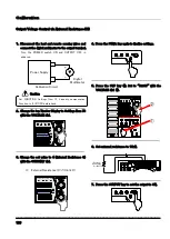
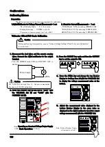
Ammeter Offset/Full-Scale Calibration
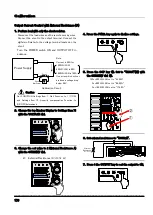
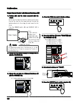
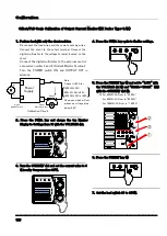
1. Perform load with only the shunt resistor.
Disconnect the load wires and the remote sensing wires.
Connect the shunt to the output terminal.
Connect the
digital multimeter to the terminal located on the shunt.
Turn the POWER switch ON and
OUTPUT OFF in
advance.
2. Press the PRESET key ① and set the CC set value
to “0.01A”(※) with the CURRENT dial ③ and the
CV set value to “1.00V” with the VOLTAGE dial ②.
※For 1600LN/LAN set to “0.1A”
(See Operating as Constant Current Power Supply
under Basic Operations on how.)
3. Press the PRESET key again and then the OUTPUT
key to set the output to ON.
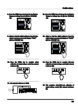
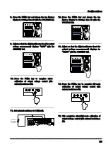
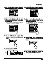
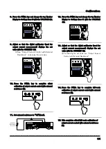
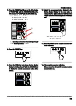
4. Press the FUNC. key and change the top Number
Display to Settings Item 26 with the VOLTAGE dial
to display the current value at the bottom.
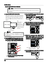
5. Adjust the measurement value displayed in the
bottom Number Display to the same value as
displayed in the digital multimeter (used for output
current measurement) with the CURRENT dial.
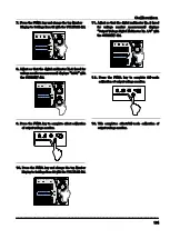
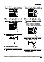
6. Press the FUNC. key to complete full-scale calibration
of the ammeter.
Set FUNCTION Settings Item 1, Sink Function, to 1 (1=ON)
and Settings Item 13, Linearity compensation Function, to
0(0=OFF)beforehand.
Caution
Note:
Current is 40A for
(400LN/LAN)
800LN/LAN is 80A
1600LN/LAN is 160A
Use wires which will not
produce a voltage drop
below 0.8V.
Calibration Circuit
CC
CV
OUTPUT POWER (%)
STEP
CURRENT
STEP
VOLTAGE
PRESET FUNC. REMOTE LOCK
20
60
100 LMT
40
80
+
-
Digital
Multimeter
Power Supply
V
Shunt
-
+
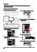
Before performing this operation, ensure “Output Current Setting Offset/Full-scale Calibration”
is carried out.
Caution
OUTPUT
PRESET
OVP
OCP
FUNC.
ALARM RESET
OUTPUT
PRESET
OVP
OCP
FUNC.
ALARM RESET
OUTPUT
PRESET
OVP
OCP
FUNC.
ALARM RESET
①
②
Note: Bottom Number Display is
displayed in Ampere(A).
CC
CV
OUTPUT POWER (%)
STEP
CURRENT
STEP
VOLTAGE
PRESET FUNC. REMOTE LOCK
20
60
100 LMT
40
80
OUT PU T
PR ES ET
OVP
OCP
POWE R
FU NC.
LOCAL
LOCK
DISPL AY
A
B
C
ST ORE
MEMOR Y
CC
CV
OUTPU T POWER
(%)
ST EP
CUR RE NT
ST EP
V OL TAGE
PRE SET FUN C. REMOTE LOCK
A LAR M R ESE T
20
60
100 LMT
40
80
①
②
③
ZX-S-400LN
Summary of Contents for ZX-S-1600LAN
Page 1: ...Constant Voltage Constant Current DC Power Supply series Instruction Manual...
Page 13: ...About this Product 10 This is blank page...
Page 63: ...Useful Function 60 This is blank page...
Page 151: ...Controlling with External Analog Contact Signals 148 This is blank page...
Page 157: ...Special Loads 154 This is blank page...
Page 199: ...Specifications 196 This is blank page...
Page 200: ...197 External Diagrams ZX S 400LN 400LAN 4 M3...
Page 201: ...Appendix 198 ZX S 800LN 800LAN...
Page 202: ...Appendix 199 ZX S 1600LN 1600LAN...


