background image

Operation and setting of M-axis (bobbin)

108

Chapter 5

RR05

1-9.

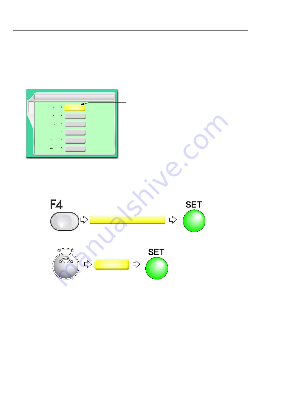
To set the maximum speed by every swing angle of M-axis 
(RPM limit following to M-axis angle)

Set the maximum speed by every swing angle of M-axis for 1-stitch.

1-9-1.  

Explanation on the screen

1-9-2.  

How to operate

The following example is for setting “RPM limit according to M-axis angle 0 to 30°” to 900 rpm.

(1) 

To open screen

(2) 

Select the value

F4

5 RPM limit following to M-axis angle

[rpm]

[rpm]

1000

30

[rpm]

490

[rpm]

390

[rpm]

340

[ ]

0

60

[ ]

31

90

[ ]

61

120

[ ]

91

[rpm]

300

150

[ ]

121

180

[ ]

151

700

The maximum rpm of the main shaft in swing angle of 
bobbin 0 to 30°

5 RPM limit following to M-axis angle

900

Summary of Contents for TLMX Series

Page 1: ...power 52 2 Thread passing fabric setting 54 3 Registration of a design in the machine memory 60 4 Decision of an embroidery design Color Change Sequence 68 5 Decision of the design start position 78 6 Check items before embroidering 85 7 Embroidery starts 91 M LMX24 E 2015 08 ...

Page 2: ...CAUTIONS To prevent any harm or damage to the person who use this product or other person we describe items that must be surely followed as below Prohibited items Items that may cause electric shock if not observed Items that must be followed carefully to ensure safe operation DANGER WARNING CAUTION Indicates that there is a lot of danger of death or serious injuries 1 if handled by mistake Indica...

Page 3: ... 1 3 TLMX L 12 2 How to use each part 13 2 1 Operation panel 13 2 2 Emergency stop switch 17 2 3 Table offset switch 18 2 4 Sleep mode key 19 2 5 Color change device 19 2 6 Option and others 20 3 Attachment 21 3 1 Embroidery method 21 3 2 Direction of bobbin 22 3 3 Display of bobbin 23 3 4 Various guides 24 3 5 Change of guide 34 3 6 Winding amount of bobbin 35 3 7 Attaching Coiling Attachment 35 ...

Page 4: ...ory 60 3 1 To use the USB memory Data Input USB 60 3 2 To use a personal computer Data Input Lan 64 4 Decision of an embroidery design Color Change Sequence 68 4 1 To decide an embroidery design Data Setting 68 4 2 To decide order of embroidery type Auto Stitch Type Selection 71 4 3 To change color automatically to start operation automatically Auto Color Change AC Auto Start AS 76 5 Decision of t...

Page 5: ...middle of stitching M axis Origin Offset 105 1 7 To set M axis Retract Position M axis Retract Position 106 1 8 To add swing angle of M axis Correction of M axis Angle 107 1 9 To set the maximum speed by every swing angle of M axis RPM limit following to M axis angle 108 1 10 To stop M axis movement in repair stitches after Frame Back M axis Retraction for Frame Back 109 1 11 To face M axis to emb...

Page 6: ...ing a Zigzag Swing Lever right and left manually Zigzag Swing 126 3 5 Setting for Coiling Coiling Setting 128 3 6 Setting for Tuck embroidery Tuck embroidery Setting 129 Chapter 6 Functions concerning embroidery 1 To perform color change to switch head 132 1 1 To perform color change manually to change embroidery mode type Manual Color Change 132 1 2 To switch right head left head manually Manual ...

Page 7: ...7 To adjust finishing of embroidering 160 7 1 To adjust driving error of the frame Backlash 160 7 2 To adjust stitch length of satin stitch Satin Stitch 161 7 3 To divide a long stitch Auto Jump 162 7 4 To change embroidering condition in every needle bar Setting in Units of Needle Bar FM head 163 7 5 To delete a fine stitch Cleanup 166 7 6 To adjust thread tension Frame start timing 167 7 7 To ma...

Page 8: ...Point 192 Chapter 7 Functions concerning frame movement 1 To return the frame Frame Back to advance the frame Frame Forward 196 1 1 To switch Frame Back Frame Forward 196 1 2 To execute by color change unit to specify number of stitches to execute 197 1 3 To change a frame feed amount of Frame Back Frame Forward FM head 199 1 4 To set All Head Sewing Start Point Frame Back All Head Sew 200 2 Neces...

Page 9: ...ion to make threading easily Table Offset Position 215 Chapter 8 Function concerning storing and deleting of design 1 Design stored in the memory of the machine 218 1 1 To delete a design Memory Delete 218 1 2 To move a design Movement of design 219 1 3 To copy a design Copy a design 220 1 4 To change the file name of the design Changing design name 222 1 5 To change a folder name Changing folder ...

Page 10: ... III Needle bar selection 256 3 4 Lochrose counter 258 Chapter 10 Countermeasure when some trouble occurs in the machine 1 Countermeasure when the machine stopped 260 1 1 Normal stop 260 1 2 Abnormal stop 261 1 3 Stop due to malfunction 264 2 Trouble examples and Corrective actions 268 2 1 Thread breakage is highly visible 268 2 2 Needle breaks 268 2 3 Bad finishing of embroidering 269 2 4 To susp...

Page 11: ...mbient noise level 288 1 3 Machine weight 289 2 Layout of electrical component card 290 3 Function code 292 4 Electrical system diagram 293 4 1 TLMX mixed type 293 4 2 TLMX triple mixed type 295 4 3 TLMX 100 T00 296 5 Terminology 298 For the software installation method refer to the separate SYSTEM HANDLING MANUAL ...

Page 12: ...er Automatic Data Set 159 10 Needle Bar Color 188 1 Maximum RPM 85 2 Total Stitch Counter Design Timer 187 3 Frame Back Frame Forward 196 5 Frame Back All Head Sew 200 6 Preset Halt 151 7 Frame Type 201 10 Stop at Lower D Point 153 1 Trace 83 2 Manual color change 132 3 Manual ATH 134 4 Return to the design start position 207 5 Manual offset 202 8 Manual Stop at Lower D Point 192 10 Needle bar ope...

Page 13: ...ATH 135 10 Upper thread lock timing 168 1 Boring 244 2 Sequin 247 Sequin Device III 2 Sequin 251 Sequin Device IV 3 Cording 243 5 Zigzag Cording Device 240 6 Lubrication 238 9 Bobbin Changer 245 10 Lochrose embroidery device 241 1 Manual M axis origin return 101 1 Manual M axis Power ON Restore 103 2 M axis Origin Offset 105 3 M axis Retract Position 106 4 Correction of M axis angle 107 5 RPM limi...

Page 14: ...181 Deleting 2 Cleanup 166 4 Move a design 219 5 Copy a design 220 6 Changing design name 222 7 Changing folder name 224 9 Data conversion for sequin output 254 6 USB Save 228 7 USB Delete 230 SET A 1 Design sort in memory 226 4 Design sort USB 232 SET F1 1 Password Functional Limit 184 3 Setting in units of Needle bar 163 SET F2 1 Max Revolution Limit 150 2 Frame Start Timing 167 3 Frame Drive Ad...

Page 15: ...sion 189 10 Language 190 SET F6 1 M axis Origin Search when data is set 111 2 Auto M axis Power ON Restore 112 3 M axis Origin Return at Color change code 113 4 Bobbin Specification 114 5 Nipple Home Position at Color change End 121 6 M axis drive start timing 115 7 Manual M axis Origin Search 104 8 Zigzag Swing Lever Protection 125 9 Nipple Lowering Speed 120 10 Automatic Thread Trimming R L Head...

Page 16: ...1 1 2 3 4 5 6 7 8 9 10 11 12 RR05 Chapter 1 Items that must be followed carefully 1 Safety Precautions 2 2 Warning labels 6 3 Inspection before starting work 7 ...

Page 17: ...round needle rotary hook take up lever pulley and speed reduction box This machine uses strong magnet The person who is mounted with internal implantable medical electronics like a pacemaker should not use this machine The person who is mounted with a equipment described above also should not access to magnet inside of this machine This internal equipment could malfunction Please read this book th...

Page 18: ...sert the power cable plug fully If a metallic part touches a blade in the plug it may cause fire and or electric shock Keep away electrical units from water and chemicals Entry or splashing of them into electrical units leads to short circuits causing fire electric shock and other troubles If water or other chemicals enter the unit Turn off the power switch shut off the primary power of the machin...

Page 19: ...selection and installation of breaker of leak current and leak current relay used for the factory are not correct malfunctioning of the machine may occur Regarding connection of power cord observe the following items Use a breaker of electric current leakage and leak current relay for which measures are taken against harmonics and surge If you use conventional breaker and relay without such measur...

Page 20: ... threads do not become disheveled Humidity 30 to 95 RH relative humidity without condensation Ambient temperature 5 to 40 C during operation 10 to 60 C during storage Avoid direct sunlight If the machine is exposed to direct sunlight over an extended period of time the machine body may be discolored or deformed Put curtains or shades to the site to prevent the machine from direct sunlight Provide ...

Page 21: ...ing warning labels for TLMX mixed type There could be danger of electric shock burning or death Persons except for service personnel designated by Tajima should not open covers When opening covers wait for four minutes after turning off the power switch A Pay attention so that you are not to be caught or put into the machine There could be danger of being caught or clipped Other persons than the s...

Page 22: ...ight have been inadequate Needle The needle might have bent The direction of needle might have been wrong The needle might have been broken Rotary hook Cleaning lubrication might have been performed in inadequate frequency Tension base switch The switch of head to use might have been turned ON The switch of unused head might have been turned OFF Needle bar suspension lever Is the lever of head to ...

Page 23: ...Inspection before starting work 8 Chapter 1 ...

Page 24: ...9 1 2 3 4 5 6 7 8 9 10 11 12 RR05 Chapter 2 Name and the way to use of each part 1 Name of each part 10 2 How to use each part 13 3 Attachment 21 ...

Page 25: ...d p 89 10 Table support 11 Border Frame 12 Rotary hook base 13 Table lid 14 Operation panel p 13 15 Power switch p 52 16 Transformer Existence absence differs depending on spec 1 Thread course 2 Main shaft motor 3 Y axis motor 4 Color change device 5 X axis motor 6 Emergency stop switch p 17 7 Bar switch p 91 8 Normal embroidery head FM head p 87 Only main sections are shown here For details refer...

Page 26: ...panel p 13 12 Power switch p 52 13 Transformer Existence absence differs depending on spec 1 Thread course 2 Main shaft motor 3 Y axis motor 4 X axis motor 5 Emergency stop switch p 17 6 Bar switch p 91 7 Lock stitch chenille head LM head p 89 8 Border Frame Only main sections are shown here For details refer to the separate parts list 2 3 4 5 6 7 8 9 10 11 5 12 13 ...

Page 27: ...ding on spec 15 Transformer Existence absence differs depending on spec 1 Main shaft motor 2 Thread course 3 Y axis motor 4 Color change device 5 X axis motor 6 Bar switch p 91 7 Table lid 8 Normal embroidery head FM head p 87 9 Lock stitch chenille head LM head p 89 Only main sections are shown here For details refer to the separate parts list 2 3 5 6 11 14 15 4 7 8 9 10 Mixed type Triple mixed t...

Page 28: ...How to use each part 13 Chapter 2 1 2 3 4 5 6 7 8 9 10 11 12 RR05 2 How to use each part 2 1 Operation panel There are two types of the following depending on model 17 inch spec 6 5 inch spec ...

Page 29: ... this manual It is illustrated as below in this manual 1 Sleep mode key p 19 Switch to power save mode To release press this key again 2 Condition of the machine AS Auto Start To perform lit Not to perform unlit FB Frame Back Forward p 92 Frame Back lit Frame Forward unlit Main shaft stop position Fixed position lit normal Other than the fixed position unlit abnormal Lower dead point or main shaft...

Page 30: ...e in the USB memory When installing the software in the machine Some type and or capacity of the USB memory may not be used for this machine In this case please buy the USB memory recommended by Tajima For details please consult the distributor Regarding use of the USB memory observe the items to notice described below Do not turn ON the machine power in the state that the USB memory is connected ...

Page 31: ...ot mistake the direction of connector The USB memory and its inside card could be damaged Do not insert the USB memory in the state that dirt and dust are attached to the inside of the connector Insert a USB memory slowly and gently Insert a USB memory upright against the port insert slot Oblique insertion could damage to inside card due to interference of connector with the card Wait for five or ...

Page 32: ...re After releasing the operation can be started as usual Specification of the machine Condition after stop How to release EN spec European safety spec The power is turned OFF 1 Turn the switch clockwise The power will be turned on 2 Start the operation Excluding EN spec and Japanese domestic use The machine will switch to the sleep mode 1 Turn the switch clockwise 2 Press the sleep mode key It tak...

Page 33: ... seconds or more After trimming threads of all heads the frame will move to the rear Since the movement of the machine after passing the thread differs depending on the switch operation perform any one of the following operations 1 Press the switch and release it immediately The frame will return to the original position 2 Press the start switch or move the bar switch to the right The frame will r...

Page 34: ...e main screen 2 Press the sleep mode key for a few seconds The sleep mode key will be lit in red 2 4 2 How to cancel the sleep mode Press the sleep mode key The sleep mode key will be unlit 2 5 Color change device The needle bar No currently selected can be checked This device is equipped only with TLMX mixed type and TLMX triple mixed type AS FB Sleep mode key An example when 2nd needle is select...

Page 35: ... how to use refer to the detail page p 82 2 6 2 Bar code reader Register a design in the memory of the machine using the bar code reader Please buy a corresponding product to the USB port We do not sell it Regarding how to use refer to the detail page p 66 When not using put it in the pocket Pocket Connect it to the USB port back face p 16 Bar code ...

Page 36: ...embroidery 4 Blind embroidery 5 Frill embroidery 6 Slub cord embroidery 7 Standing embroidery 3 1 2 Zigzag Swing Stitch 1 Pattern 4 2 Pattern 5 3 Pattern 6 4 Pattern 7 5 Pattern 8 6 Pattern 9 3 1 3 Coiling 1 1 1 2 1 2 3 1 3 4 1 4 3 1 4 Tuck For details refer to the separate manual TUCK EMBROIDERY Standing embroidery Pattern 5 Zigzag Swing Stitch Taping 1 2 Coiling Tuck Taping Zigzag Swing Stitch C...

Page 37: ...his state is called stand by position M axis origin 2 The position of bobbin at suspended head tension base switch turned OFF is as per the figure below This state is called retracting position the retracting position can be changed by the selection of M axis angle 0 or 90 When changing the retracting position refer to the detailed page p 106 0 352 7 178 4 M 90 M axis angle Zigzag Swing Stitch Tap...

Page 38: ...ters r l w in the figure below Mixed type Triple mixed type 100 1 T00 1 100 is usually set to All head sewing In case of frame spec W use right head and left head separately 100 T00 at all head sewing 14117 0 R R Z7 3 9 r T 2 R Z4 2 850 352 7 178 4 0 The figure below is a display sample of TLMX mixed type The bobbin at standard side is selected now In step 3 the bobbin at reverse side is selected ...

Page 39: ...drive to M axis bobbin p 101 c To move up down nipple manually p 101 About guide fixing screw Three kinds of screw are packed with the machine the figure below Regarding screw attaching spot refer to the figure below to avoid mistake Do not use 4 mm or 5 mm screw at position A in the right figure Only possible to use 3 mm screw Wrong usage of screw will break the parts 3 mm 4 mm 5 mm With cord hol...

Page 40: ... screw 3 Cord holder accessory It is used for holding tape or cord 4 Guide A 5 Tape guide A mm B mm C mm TL 1 3 5 4 5 0 3 TL 2 8 0 9 0 0 3 TL 3 4 0 5 0 1 0 TL 4 4 0 5 0 0 3 TL 5 3 5 4 5 1 5 TL 6 9 0 10 0 0 3 TL 7 5 0 6 0 1 7 TL 8 5 0 6 0 1 0 TL 9 2 0 3 0 2 5 TL 10 3 0 4 0 2 0 TL 11 6 0 7 0 1 8 TL 12 9 0 10 0 2 0 TL 13 5 0 6 0 2 8 TL 14 2 0 3 0 2 0 TL 15 3 0 4 0 2 5 3 mm 5 mm B C A Various kinds of...

Page 41: ...broidery Setting on the operation panel in the following embroidery methods is T p 71 1 Set screw 2 Set screw 3 Cord presser one kind only 4 Guide B 3 mm 4 mm Various types of Size A mm are available 1 0 1 2 1 5 2 0 2 5 3 0 A 1 2 2 3 4 RR05 ...

Page 42: ...ting type tape guide for frill embroidery There are following two types of the size depending on the adjustment width A in the figure below A 10 to 25 mm 20 to 50 mm 3 Straight adjusting type tape guide There are following two types of the size depending on the adjustment width B in the figure below B 10 to 25 mm 20 to 50 mm 4 Guide A 5 Tape guide bar 3 mm 5 mm Size A Dimension B Block Screw Screw...

Page 43: ...justing type How to adjust Loosen the screws to adjust the position of block to the tape width 1 Set screw 2 Set screw 3 Bent adjusting type tape guide Adjustment width 20 to 50mm 4 Guide A 5 Tape guide bar 3 mm 5 mm Block Screw Screw Block 1 2 3 4 5 RR05 ...

Page 44: ...anel in the following embroidery methods is T p 71 Set M axis origin offset to 180 p 105 1 Set screw 2 Set screw 3 Cord guide for blind embroidery 4 Guide C 5 Hexagon socket head set screw Adjust the fixing degree tilt of guide C 3 mm 4 mm Various types of Size A mm are available A Guide C 1 2 3 4 5 RR05 ...

Page 45: ...option Setting on operation panel for this embroidery method is T p 71 1 2 3 4 1 Set screw 2 Set screw 3 Slub cord cord guide 4 Slub cord guide 3 mm 4 mm Two types of Size A mm are available 2 0 3 0 A 2 1 Set screw 2 Set screw 3 Standing embroidery guide 4 Exclusive nipple for standing embroidery 3 mm 4 mm 2 types of size mm 1 0 4 0 1 3 3 0 1 4 2 2 3 RR05 ...

Page 46: ...ed as follows Upper thread 2 Under thread Unit 0 Under thread Ratio 30 When mis detection of upper thread breakage occurs in above setting change detecting sensitivity of Upper thread When mis detection occurs while using the setting of Under Unit by the value except 0 return to 0 1 Set screw 2 Set screw 3 Frill presser plate one type only 4 Frill guide 5 Guide A 3 mm 4 mm Various types of Size A ...

Page 47: ... Chart 1 Chart 2 1 Set screw 2 Set screw 3 Guide A 4 2 kinds of cord guide Cord guide holder Cord guide holder C Refer to the chart below 5 Cord guide Various kinds of size Refer to the chart below Cord guide holder Cord guide Cord guide holder C Cord guide 3 mm 4 mm 2 5 1 0 1 5 2 0 Unit mm 2 5 3 0 3 1 3 3 3 5 2 5 3 5 4 0 5 0 RR05 ...

Page 48: ...1 11 Tuck embroidery For details refer to the separate manual TUCK EMBROIDERY Setting on operation panel for this embroidery method is H p 71 1 4 1 Cord guide Various kinds of size Refer to Chart 1 9 2 Set screw 3 Set screw 4 Guide D 3 mm 4 mm 2 3 1 2 1 Tuck embroidery attachment 2 Guide A Feed attachment Guide attachment RR05 ...

Page 49: ...f the screw 3 Chart 1 After fixing the guide 2 by using the screw 1temporarily fix the tape guide 4 to the nipple 5 by using the screw 3 temporarily 2 Align the convex part 8 of the guide gauge with the grooved part of the nipple 7 Align the needle hole of the guide 9 with the apex of the conical pin 10 and then tighten the screws 1 and 3 2 4 6 1 3 5 Chart 1 Screw 1 Screw 3 existence absence of a ...

Page 50: ... bobbin code no 347 is displayed and the machine will stop 3 7 Attaching Coiling Attachment 3 7 1 How to attach 1 Remove the screw 1 to detach the bobbin 2 Bobbin Application Bobbin weight per piece Standard bobbin Taping Zigzag Swing Stitch 100 g or less 1 1 The weight of double bobbin is about 200g Bobbin 2 pcs x 100g Small bobbin Coiling 50 g or less Standard bobbin Small bobbin Small bobbin is...

Page 51: ...rew 8 and the screw 9 Please note that the length of screw 8 and screw 9 is different 4 Attach the attachment for coiling and loosen the screw 11 Attach the attachment for coiling 10 to the size of Pin hole size small 3 4 5 6 7 8 9 Chart 1 Screw 8 Screw 9 3 mm 4 mm 10 11 Pin hole size Large Pin hole size small Flat fillister head screw 9 64 40 12 RR05 ...

Page 52: ...ould not touch the needle plate Loosen the screw 13 to adjust the attaching position of the cord holder 12 Adjust the cord guide 14 by using the screw 15 so that it does not touch the guide 7 3 7 2 How to pass the material 1 Face the bobbin bracket 1 to the front Detach the plate spring 2 from the pin 3 2 Set the bobbin 4 to the bracket 1 12 13 14 7 15 2 1 3 4 1 RR05 ...

Page 53: ... Chapter 2 3 Return the plate spring 2 to the original position 4 Pass the material to each section referring to the figure below 2 Retract the cord guide holder 5 and pass the material to the cord guide 6 5 6 RR05 ...

Page 54: ...3 8 1 Attaching 1 Attach the double bobbin 1 and loosen the screw 2 2 1 Hexagon socket head cap screw M4 10 In the state of attached The roller 3 is fitted to the arm holder 4 The connecting block 5 is fitted to the groove 6 of the nipple 3 4 5 6 Pin hole size Large Pin hole size Small RR05 ...

Page 55: ...plate Loosen the screw 8 to adjust the attaching position of the cord holder 7 The gap of the cord guide 9 and the guide 10 should be 2mm to 3 mm Loosen the screw 11 to adjust the attaching position of the cord guide 9 3 8 2 How to pass the material 1 Detach the plate spring 1 from the pin 2 2 Set the bobbin 3 and return the plate spring 1 7 8 9 10 11 A 1 2 1 3 RR05 ...

Page 56: ...ulled smoothly 4 Pass the material 6 7 referring to the chart below Bobbin stopper 5 accessory is the bracket for fixing the bobbin not used 5 4 Zigzag Swing Stitch Put the material in the groove 8 of tension stud Excluding flat material slub cord etc Some parts are detached for explanation in the photo below 8 Taping 6 7 Example for using Cord holder 9 9 RR05 ...

Page 57: ... Z6 When selecting this pattern using data of regular running stitch needle will be located three times at the same point and zigzag swing lever will swing back and forth one time Two pieces of upper thread will be sewn at right angles to direction of movement 4 Zigzag swing 7 Z7 It needs mixed data of zigzag and direct run Zigzag swing lever swings to the same direction at zigzag proceeding part ...

Page 58: ...d will be sewn at right angles to direction of movement 6 Zigzag swing 9 Z9 When selecting this pattern using data of regular running stitch needle will be located twice at the same point at first and be advanced by data to be located once next and be further advanced by data to be located twice again One piece of upper thread will be sewn at the right angles to direction of movement When using th...

Page 59: ...Attachment 44 Chapter 2 ...

Page 60: ... E 45 1 2 3 4 5 6 7 8 9 10 11 12 RR05 Chapter 3 Screen 1 Screen display 46 2 Message display 49 ...

Page 61: ... figure A 5 M axis Origin Offset p 105 With setting 6 Setting for Automatic Offset p 209 Existence Absence 7 Step p 71 8 Setting to return the frame to the front during embroidery p 212 With setting 9 Forced start p 72 With setting 10 Frame that is currently set Border frame AFC option 11 Current number of stitches 12 Maximum RPM of the head that is currently selected p 85 13 The current M axis an...

Page 62: ...on 3 Data Conversion 4 Repeat 5 Automatic Offset 6 A S after Auto Data Set 10 Needle Bar Color 1 1 Select YES NO by using the jog dial and press SET key To lower the cursor press SET key or AFrame To return the screen press the E key YES B AC YES NO AS YES NO YES NO Auto Start NO NO NO 1 1 Auto Color Change AC Auto Start AS at Same Color 1 File name up to 8 characters 2 To return the cursor to del...

Page 63: ...11 FM Upper T Detection FM Under T Detection Unit FM Under T D Step Ratio Auto Color Change AC Auto Start AS A S after Auto Data Set Auto Origin Return 70 4 1 Design of which data is set to be embroidered from now 2 File name 3 Design size Design Start Point starting position of design 4 The number of total stitches of design 5 Current frame position Distance from the design start point 6 Current ...

Page 64: ...at T3 T2 T of the design About T2 One design will be generated by three types of file indication TAJIMA_W CT0 TAJIMA_W DGF TAJIMA_W TBF Therefore please handle these three files as three sets Saving format Indication in a personal computer Application T3 TAJIMA_W TCF Data integrating CT0 DGF and TBF of T2 T2 TAJIMA_W CT0 Color Change Sequence Design Start Point TAJIMA_W DGF Design data on a person...

Page 65: ...eat of design 5 Automatic Offset The message shown left will be displayed only when the machine reads condition data at 2 1 This message is displayed when setting data of design Design start position means the frame position where this design was started embroidering last time OK to move a frame to the Start Point of Design Data X 115 7 Y 153 2 YES SET NO E These figures mean the place to move of ...

Page 66: ... ON the power 52 2 Thread passing fabric setting 54 3 Registration of a design in the machine memory 60 4 Decision of an embroidery design Color Change Sequence 68 5 Decision of the design start position 78 6 Check items before embroidering 85 7 Embroidery starts 91 ...

Page 67: ...wing types of the power switch depending on the model Do not turn ON the machine power in the state that the USB memory is connected to the operation panel except when installing the software in the machine The system sometimes may not start up ON OFF ON OFF CAUTION This type can be locked ...

Page 68: ... R I P P E D Handle Groove Lock plate Commercial 1 Turn the handle toward direction A to the position of the groove 2 Push the lock plate to the direction indicated by a big arrow and return the handle to the direction B the original position 3 Lock item Award modular BIOS Press DEL to set up Now System Loading 40 Windows CE net Microsoft TLMX Main screen Software version installed in the machine ...

Page 69: ...ic setting 54 Chapter 4 RR05 2 Thread passing fabric setting 2 1 Pass the thread 2 1 1 FM head Threading at tension part indicated by arrows affects finishing of embroidering Therefore thread correctly Threading Accessory ...

Page 70: ...thread tension would be affected badly Return the adjusting lever to the original position after passing the thread Otherwise thread breakage would be caused or the thread tension would be affected badly Upper thread lock Thread take up spring 1 2 3 4 How to use adjusting lever 1 Raise the lever 2 Pass the thread 3 After threading return the lever The screw faces to the front Lever Screw Lever CAU...

Page 71: ...reading at tension part indicated by arrows affects finishing of embroidering Therefore thread correctly Sewing thread Core thread for coiling To nipple Use a threader TLMX 100 T00 Normal embroidery N of TLMX mixed type Except normal embroidery N of TLMX mixed type ...

Page 72: ...ffect the thread tension badly Return the adjusting lever to the original position after passing the thread Otherwise thread breakage would be caused or the thread tension would be affected badly How to use adjusting lever 1 Raise the lever 2 Pass the thread 3 After threading return the lever The screw faces to the front Lever Screw Lever Sewing thread Use a threader CAUTION ...

Page 73: ...ension more strongly attach the take up adjuster by using the screws as shown in figure A The attaching position of take up adjuster differs depending on the type of rotary hook Take up Adjuster Figure A Raising the take up adjuster from the position shown the above figures will make the thread tension stronger furthermore Jumbo rotary hook Regular rotary hook Screw ...

Page 74: ...iful or to perform efficient works by reducing the thread breakage it is important to stretch the fabric correctly on the embroidery frame Fix fully stretched fabric without any line The number of clips and their length differ depending on the frame size Attach the clips evenly by minimizing the interval between clips Clip How to fit in a clip Inside Outside ...

Page 75: ...r designs which can be read in one layer directory is 255 designs at the maximum b Folder Group1 Group2 T TBF T2 TBF T TBF T3 TBF T TBF T2 TBF T2 TBF T TBF T TBF T3 TBF T TBF T2 TBF T3 TBF T TBF T3 TBF T2 TBF T TBF T TBF T3 TBF T2 TBF 4 Data Input USB A Layer directory a Folder b Design c Folders and designs stored in the USB memory will be displayed The design except the one shown at left will be...

Page 76: ... based on 17 inch operation panel for convenience 1 To set USB memory 2 To open screen G001 TCF TAJIMA_W 14117 The number of Extension File name Within 1 000 000 stitches The extension differs depending on a saving format of the design T3 TCF T2 TBF T DST For saving format of the design refer to the detail page p 49 Design name T3 Saving format Up to 8 characters of design total stitches of design...

Page 77: ...e design a Design in a folder b Design on the screen Pressing SET will display the folder or the design in the second layer directory To return to the original layer directory press E key T3 G001 TCF TAJIMA_W 14117 Pressing i key will display the design confirmation screen p 48 To return the original screen press E key G001 TCF TAJIMA_W 14117 ...

Page 78: ...a design in the memory of the machine Are you ready Read Condition Data If a saving format of the design is T3 or T2 the following message will appear After that proceed to To decide an embroidery design Data Setting p 68 Condition data means Color Change Sequence and Design Start Position 1 Data Input Memory A ...

Page 79: ...on For details please consult the distributor 3 2 1 Explanation on the screen 3 2 2 How to operate not to use the bar code reader The following is an example when registering a design stored in a personal computer in the memory of the machine 1 After connecting the LAN cable to the LAN port at the back of the operation panel start up DG ML by Pulse 2 Check if network setting is YES p 239 3 To open...

Page 80: ...design in the memory of the machine This design has become the state that it is possible to embroider Data set is completed After that proceed to To change color automatically to start operation automatically Auto Color Change AC Auto Start AS p 76 TBF 3 Are you ready Read Condition Data Condition data means the Color Change Sequence ...

Page 81: ...e reader to the USB port of the operation panel p 16 4 Set the screen to the main screen 5 Read the bar code Condition data Color Change Sequence is also read automatically This design has become the state that it is possible to embroider Data set is completed After that proceed to To change color automatically to start operation automatically Auto Color Change AC Auto Start AS p 76 Please buy a c...

Page 82: ...r Deal with the following procedure If the problem is not solved please consult the distributor Error code No BC1 Press E key Resetting error Design data transmission to Spooler Rereading of the bar code A 5 Switch to data input LAN screen and select the design manually Press SET key Completion of data set To perform Not to perform Transmit design data to Spooler Rereading of the bar code Success ...

Page 83: ...e can be changed p 224 c Design registered in the memory of the machine 1 Data Input Memory A c b a Layer Folder Design registered in the memory of the machine directory The capacity of the machine memory is as below 17 inch spec 200 designs at the maximum Up to 1 500 000 stitches 6 5 inch spec 200 designs at the maximum Up to 2 000 000 stitches First layer directory Second layer directory Design ...

Page 84: ...oider 1 To open screen 2 To select a design The operation differs depending on a storing place for the design a Design in a folder b Design on the screen 1 Data Input Memory Pressing SET will display the folder or the design in the second layer directory To return to the original layer directory press E key 3 Pressing i key will display the design confirmation screen p 48 To return the original sc...

Page 85: ...design When performing this operation do not put your hands etc on the machine table Moving the frame could injure you Are you ready OK to move a frame to the Start Point of Design Data When the move of the frame is not desired Pressing SET will move the frame then data set will be completed CAUTION ...

Page 86: ...ed step 2 2 Auto Stitch Type Selection 1 2 3 4 5 6 1 2 3 4 5 6 a c Design to be embroidered from now b Step Offset mark d Forced start mark Nipple stroke p 118 0 Do not stroke 1 to 8 Do stroke The amount of stroke differs depending on the value R means that the bobbin at standard side of LM head is selected The above figure is an example of TLMX mixed type For the other models refer to the detaile...

Page 87: ...necessary p 209 d Forced start mark Auto start at same color is performed even if the setting of Auto start at same color is NO 1 15 Step No Needle bar color p 188 FM head An example of 15th needle of FM head selected Change Sequin 1 and 2 p 256 Right side Left side 1 2 1 2 Sequin 2 Sequin 1 2 1 2 9 Select 1 when step 2 will be embroidered at the right device Select 9 when step 2 will be embroider...

Page 88: ...in the conditions below 1 To open screen 2 To select Step 2 3 To select bobbin R at standard side 4 To select the embroidery mode Taping 5 To select nipple stroke 3 R r LM Bobbin at standard side Bobbin Bobbin at standard side Embroidery mode Taping Nipple stroke 3 2 Auto Stitch Type Selection 2 r Z7 6 2 R Z7 6 Bobbin at standard side 2 R T 6 Taping 2 R T 3 Nipple stroke 3 ...

Page 89: ...will switch automatically 4 2 3 How to operate The following is an example when setting step 1 to the needle bar No 4 1 To open screen 2 To select the needle bar No to use at the step 1 In case of TLMX mixed type TLMX triple mixed type TLMX T00 the motion when starting the machine after that is as per the following a When it is in the middle of embroidery When the current head is different from se...

Page 90: ...How to operate The following is an example to insert the offset mark or the forced offset mark between step 2 and step 3 1 To select the step to insert the offset mark 2 To insert the offset mark 3 To delete the offset mark 4 To insert the forced offset mark 2 9 3 1 2 9 3 1 Blinking 2 9 3 1 2 9 3 1 Blinking ...

Page 91: ...the head of Auto Stitch Type Selection is different from the current head the frame will move to the neighbor head after start of the machine fixed interval movement b Setting to start operation automatically after color change YES To perform NO Not to perform Selecting NO will disable the following settings c Setting to start operation automatically when the same needle bar No is selected at the ...

Page 92: ... 2 How to operate The following example is for setting below three kinds of conditions Automatic Color Change AC Automatic Start AS Automatic Start at the same color 1 To open screen 2 Automatic Color Change AC 3 Automatic Start AS 4 Automatic Start at the same color 1 Auto Color Change Auto YES YES YES ...

Page 93: ...y Current position Stitch Counter Function Stitch Length Design Counter Step OFFSET Data conversion Rotation Reversion Repeat M Repeat 0 88 4 0 0 59 6 59 2 From Design Start Point 1 8 3 10 5 7 2 7 8 4 80 3 3 130 0 pp 0 0 G0041 W Tajima 14117 st 80 100 0 0 0 0 0 Design to be Design repetition Scaling up down reversion of design Size of design mm 88 4 59 6 59 2 Start position of design The size base...

Page 94: ...on on the screen 5 2 2 How to operate The following is an example of lowering the needle bar 1 To open screen 2 To lower needle bar When performing this operation do not put your hands etc near the needle Moving up down of the needle bar could injure you Up To raise needle bar Down To lower needle bar 10 Needle bar operation Up CAUTION 10 Needle bar operation Up Pressing SET key will lower the nee...

Page 95: ...anation on the screen Main screen Relation between frame travel direction and code 1 If the frame moves to the rear the mark will be Y 2 If the frame moves to the front the mark will be Y 3 If the frame moves to the right the mark will be X 4 If the frame moves to the left the mark will be X X X Y Y The current frame position is displayed by the numerical value mm The frame position is based on th...

Page 96: ...e 2 To use Jog dial Jog shuttle a Switch to main screen Press E key plural times to switch to the main screen b To decide the frame travel direction Press E key to decide the frame travel direction When performing this operation do not put your hands etc on the machine table Moving the frame could injure you CAUTION Speed switching key Rear Left Front Right When you want to change the frame travel...

Page 97: ...huttle high speed The frame will move 3 To use Jog remote controller Option a Switch to main screen Press E key plural times to switch to the main screen b To move the frame to design start position Tilt the stick The frame will move Jog dial Jog shuttle Stick Frame travel speed will be changed by degree of leaning condition of the stick ...

Page 98: ...eration do not put your hands etc on the machine table Moving the frame could injure you 1 2 3 4 5 6 7 Start position of design The number in the left picture indicates the orbit of the frame After completion of trace embroidering from that position is possible When repeat is set The machine will trace the whole designs after tracing the first design When automatic offset is set The machine traces...

Page 99: ...r temporary stop b Code No 225 will be displayed Press E key c Move the frame to the design start position d Perform tracing again To interrupt trace follow the procedure below a Suspend the operation by the bar switch or the stop switch Code No 1C1 will be displayed Do not turn OFF while code No 1C1 is displayed b Press E key c After that follow the message described below Low YES SET NO E OK to ...

Page 100: ...ay column During stop The maximum speed is displayed During operation Actual operating speed is displayed rpm 4 0 A 12 0 B C mm 0 rpm 1 Maximum RPM C rpm LM 850 850 Normal Embroidery Taping rpm 850 Zigzag Swing Stitch rpm 450 Coiling 1 1 rpm 450 Coiling 1 2 rpm 450 Coiling 1 3 rpm 450 Coiling 1 4 rpm Tuck rpm N FM C 1 Maximum RPM 850 Maximum RPM of LM head Coiling When setting Coiling to 500 rpm i...

Page 101: ... to 950 1 To open screen 2 Select maximum speed Selection of the value exceeding Max Revolution Limit is not possible To change the maximum speed during operation of the machine turn the jog dial the jog shuttle 1 Maximum RPM 950 While turning the jog dial the following display appears The number described in is the maximum speed 850 ...

Page 102: ...tion during operation of the machine is invalid Even if the switch manipulation is executed it will become effective after the machine stops Tension base switch Green Red Unlit Lit OFF Thread breakage indicator lamp Lit in green Embroidery is possible When FM head is selected Unlit Embroidery is suspended Needle bar will not move down When LM head is selected Blinking in green Frame back section a...

Page 103: ...fore embroidering 88 Chapter 4 RR05 2 Needle bar suspension lever This lever will suspend the head mechanically ON Embroidery is possible OFF Embroidery is suspended It is located at the left side of the head Switch ...

Page 104: ...s performed it will become effective after the machine stops ON OFF Tension base switch Thread breakage indicator lamp Lit in green Embroidery is possible When LM head is selected Unlit Embroidery is suspended Needle bar will not move down When FM head is selected The nipple will move up and the bobbin will return to the retractable position Blinking in green Frame back section at the head without...

Page 105: ...Attachment Attach attachments guide bobbin bracket according to stitch type embroidery method Fix the end of material by using tape so that sewing of the material becomes stable After start of the machine stop the machine once and cut the end of the material ...

Page 106: ...tion Returning to the original position will start normal operation 7 1 2 Start stop switch This switch is equipped in some models 1 When starting the operation press the start switch 2 To stop the machine press the stop switch 3 To start slow operation keep on pressing the start switch Releasing it will start normal operation Before starting the machine pay enough attention to the surrounding saf...

Page 107: ...int when you want to start from the middle of embroidery There are following two types of execution of Frame Back Forward 1 Operation by operation panel The machine will execute FB FF by color change unit or by specifying the number of stitches p 197 2 Operation by bar switch or stop switch The machine will execute FB FF by 1 stitch or setting unit Explanation is given as follows Current setting c...

Page 108: ...it depending on the current setting condition Move the bar switch to the left and keep at that position during stop The machine will continue FB FF by 1 stitch unit in case within 10 stitches Returning to the original position will suspend FB FF The machine will continue FB FF by setting unit in case of 11 stitches or more 1 Returning to the original position will not suspend the machine operation...

Page 109: ...tch and release immediately during stop Frame Back or Frame Forward will be performed by 1 stitch unit depending on the current setting condition Keep on pressing the stop switch during stop The machine will continue FB FF by 1 stitch unit in case within 10 stitches Releasing it will suspend FB FF The machine will continue FB FF by setting unit in case of 11 stitches or more 1 Releasing it will no...

Page 110: ...tarting stitches after frame back differ between the head with thread breakage and the head without thread breakage Head with thread breakage The machine restarts embroidery from the position where Frame Back stopped 1 in the figure below As a result repair stitches will be performed at the position 2 with missing stitches due to thread breakage 291 1 Stop by detecting thread breakage Reset E Code...

Page 111: ...ead to the Top once when you release the switch it will return to the original position However if M axis retraction for frame back is set to YES in LM head set the tension base switch of the head to the Top once before the start of frame back so that the embroidery in the head without thread breakage can be performed from the position where frame back is stopped Position where Frame Back started ...

Page 112: ...automatic offset 2 If LM head is selected The machine will stop a Cut the material and upper thread by using scissors etc b When starting the machine the frame will move according to the setting of automatic offset Rerer to Fig 1 Fig 1 Setting for Automatic Offset With Without The frame will move to the offset start position E E End position of design The frame will not move However when automatic...

Page 113: ...Embroidery starts 98 Chapter 4 ...

Page 114: ...99 1 2 3 4 5 6 7 8 9 10 11 12 RR05 Chapter 5 Functions concerning LM head 1 Operation and setting of M axis bobbin 100 2 Operation and setting of Nipple 116 3 Operation and setting for embroidering 122 ...

Page 115: ...2 Turn Jog shuttle or Jog dial while pressing the set key The bobbin will turn to the rotating direction of shuttle It is possible to start the machine from the position after rotating the bobbin When performing this operation do not put your hands etc near the needle Rotating bobbin could injure you CAUTION Jog shuttle Jog dial High speed rpm Low speed rpm Bobbin ...

Page 116: ...king When releasing the drive Move up the tension base switch to Top once The bobbin and nipple will return to the original position 1 3 To return M axis to the origin manually Manual M axis Origin Return The origin is the position where bobbin rotates and stops just after data set and at thread breakage Stand by position 1 3 1 Explanation on the screen Tension base switch Lamp Bobbin Nipple F4 1 ...

Page 117: ... 3 2 How to operate The following example is for executing manual M axis origin return 1 To open screen 2 To execute When performing this operation do not put your hands etc near the needle Rotating bobbin could injure you CAUTION 1 Manual M axis origin return ...

Page 118: ...f the bobbin by hand at power turned OFF It is effective only when misaligned angle against the correct angle is less than 180 1 4 1 Explanation on the screen 1 4 2 How to operate The following example is for executing manual M axis power on restore 1 To open screen 2 To select power resume 3 To execute When performing this operation do not put your hands etc near the needle Rotating bobbin could ...

Page 119: ...r executing manual M axis origin search 1 Set the screen to the main screen 2 Press the F6 key while pressing the SET key 3 Press F6 key 4 To execute When performing this operation do not put your hands etc near the needle Rotating bobbin could injure you M axis origin search To execute Not to execute 7 Manual M axis Origin Search CAUTION SET F6 screen will be displayed 7 Manual M axis Origin Sear...

Page 120: ...he setting value to the direction of the design data In case of Blind embroidery set this value to 180 In other cases it is unnecessary to change this value in normal use 1 6 1 Explanation on the screen 1 6 2 How to operate The following example is for setting M axis origin offset to 180 1 To open screen 2 Select the value It shows M axis angle direction of bobbin 2 M axis Origin Offset 0 2 M axis...

Page 121: ... the direction of bobbin at the suspended head thread breakage indicator lamp is unlit 1 7 1 Explanation on the screen 1 7 2 How to operate The following example is for setting M axis retracting position to 90 1 To open screen 2 Select the value It shows M axis angle direction of bobbin 3 M axis Retract Position 0 3 M axis Retract Position 90 ...

Page 122: ...s located to inner part of material Therefore by increasing decreasing swing angle of M axis against design data it corrects needle locating position Do not use data that includes swing angle of 120 or more of design data The maximum swing angle to be added is 60 1 8 1 Explanation on the screen 1 8 2 How to operate The following example is for setting Correction of M axis angle to 90 1 To open scr...

Page 123: ... 1 9 1 Explanation on the screen 1 9 2 How to operate The following example is for setting RPM limit according to M axis angle 0 to 30 to 900 rpm 1 To open screen 2 Select the value F4 5 RPM limit following to M axis angle rpm rpm 1000 30 rpm 490 rpm 390 rpm 340 0 60 31 90 61 120 91 rpm 300 150 121 180 151 700 The maximum rpm of the main shaft in swing angle of bobbin 0 to 30 5 RPM limit following...

Page 124: ...bbin and nipple of head at which thread is not broken will move to the retracting position In addition it is not possible to perform the following operations of tension base switch at head without thread breakage a Set bobbin free b Set to mending head 1 10 1 Explanation on the screen 1 10 2 How to operate The following example is for setting M axis retraction for frame back 1 To open screen 2 To ...

Page 125: ...hange code After setting material here restarting the machine will start embroidery Since it is possible to set material with bobbin facing to sewing direction it prevents mis stitching at start 1 11 1 Explanation on the screen 1 11 2 How to operate The following example is for setting Control of M axis start direction 1 To open screen 2 To set Control of M axis start direction YES To perform NO N...

Page 126: ...gle after data set and returns bobbin to the stand by position 1 12 1 Explanation on the screen 1 12 2 How to operate The following example is for setting M axis origin search when data is set 1 Set the screen to the main screen 2 Press the F6 key while pressing the SET key 3 To set M axis origin search YES To perform NO Not to perform 1 M axis Origin Search when data is set NO SET F6 screen will ...

Page 127: ...misaligned due to turning of the bobbin by hand at power turned OFF It is effective only when misaligned angle against the correct angle is less than 180 1 13 1 Explanation on the screen 1 13 2 How to operate The following example is for setting Auto M axis power ON restore 1 Set the screen to the main screen 2 Press the F6 key while pressing the SET key 3 Press F6 key 4 To set M axis power restor...

Page 128: ...stop by color change code 1 14 1 Explanation on the screen 1 14 2 How to operate The following example is for setting M axis origin return at stop code 1 Set the screen to the main screen 2 Press the F6 key while pressing the SET key 3 Press F6 key 4 To set M axis origin return YES To perform NO Not to perform 3 M axis Origin Return at Color change code NO SET F6 screen will be displayed 3 M axis ...

Page 129: ... following example is for setting type of bobbin to Double bobbin 1 Set the screen to the main screen 2 Press the F6 key while pressing the SET key 3 Press F6 key 4 To set Bobbin Specification Double Double bobbin Single Single bobbin Reel Heater wire feeding device 4 Bobbin Specification Double SET F6 screen will be displayed 4 Bobbin Specification Double RR05 ...

Page 130: ...ction when you want to change texture of embroidery in taping etc 1 16 1 Explanation on the screen 1 16 2 How to operate The following example is for setting M axis drive start timing to 170 1 Set the screen to the main screen 2 Press the F6 key while pressing the SET key 3 Press F6 key 4 Select the value M axis drive start timing 120 170 220 6 M axis drive start timing 120 SET F6 screen will be d...

Page 131: ... the main screen 2 Press the E key while pressing the Set key When performing this operation do not put your hands etc near the needle Since the nipple moves up and down you could be injured CAUTION Lower position Upper position Lower position will become the height of nipple stroke that is currently set Nipple of head does not work of which tension base switch is set to bottom position RR05 ...

Page 132: ... Color Change to NO 2 2 1 Explanation on the screen 2 2 2 How to operate The following example is for setting Manual nipple stroke adjustment to 3 1 To open screen 2 Select the value Do not stroke 1 Manual Nipple Stroke Adjustment NO Nipple stroke 0 Do stroke according to the value of Nipple stroke amount p 118 1 to 8 Nipple will move up After start of the machine the value prior to selecting H wi...

Page 133: ...ting Nipple stroke amount of Nipple stroke 1 to 1 5mm 1 To open screen 2 To select the value F6 2 Nipple setting Nipple Stroke Amount 1 2 mm mm 1 0 2 0 3 mm 3 0 4 mm 4 0 5 mm 5 0 6 mm 6 0 7 mm 7 0 8 mm 8 0 0 2 mm mm 0 5 0 5 3 mm 0 5 4 mm 0 5 5 mm 0 5 6 mm 0 5 7 mm 0 5 8 mm 0 5 1 mm 0 5 Lower Dead Point Nipple Stroke Amount The actual stroke amount becomes bigger than the set value by 1 to 3 mm acc...

Page 134: ... Nipple lower dead point of Nipple stroke 1 to 0 3mm 1 To open screen 2 To select Nipple stroke 1 of nipple lower dead point 3 To select the value F6 2 Nipple setting Nipple Stroke Amount 1 2 mm mm 1 0 2 0 3 mm 3 0 4 mm 4 0 5 mm 5 0 6 mm 6 0 7 mm 7 0 8 mm 8 0 0 2 mm mm 0 5 0 5 3 mm 0 5 4 mm 0 5 5 mm 0 5 6 mm 0 5 7 mm 0 5 8 mm 0 5 1 mm 0 5 Lower Dead Point Lower Dead Point The smaller the value the...

Page 135: ...2 5 2 How to operate The following example is for setting Nipple lowering speed to Low 1 Set the screen to the main screen 2 Press the F6 key while pressing the SET key 3 Press F6 key 4 To set Nipple Lowering Speed High High speed Low Low speed Lowering speed by operation of the tension base switch is excluded 9 Nipple Lowering Speed High SET F6 screen will be displayed 9 Nipple Lowering speed Low...

Page 136: ... nipple by color change code 1 Set the screen to the main screen 2 Press the F6 key while pressing the SET key 3 Press F6 key 4 Select the value SET 5 Nipple Home Position at Color change End F6 Color change End High Low High Low Low Low Movement of nipple at Color change code High Upper position Low not to work Movement of nipple at End code High Upper position Low not to work SET F6 screen will ...

Page 137: ...nly to TLMX 100 and T00 3 1 1 Explanation on the screen 3 1 2 How to operate The following example is for executing Manual thread tension setting 1 To open screen 2 To execute Stitch type Upper thread tension Normal Embroidery Loosen Taping coiling zigzag swing embroidery Tighten Manual Thread Tension Setting To execute Not to execute 8 Manual Thread Tension Setting 8 Manual Thread Tension Setting...

Page 138: ...m 0 0 All 16 ZigzagSwingStroke 16 SwingAssist 0 30 Retract Zigzag Swing All FNC 0 NO Pattern5 7 Width of Material 0 2 YES NO Distance 12 7 0 2 12 7 mm 0 0 12 7 mm 0 a Swing angle at the tip of Zigzag swing lever mm b Swing angle of bobbin to be added c Retract Zigzag Swing d Data generation of Zigzag Swing e Width of Material f Frame moving amount Datageneration Zigzag swing lever Actual stitch le...

Page 139: ...not cope with by moving the frame zigzag NO Data generation is not executed e With of material e in the above figure f Frame moving amount f in the above figure Select the value not longer than a stitch length in design 3 2 2 Explanation for operation The following example is for setting the stroke of zigzag swing to 10 1 To open screen 2 Select the value Zigzag swing 5 Design data e Only code is ...

Page 140: ...xed interval moving Some nipping degree or position of clip may not be possible to retract the lever This function does not apply to TLMX 100 3 3 1 Explanation on the screen 3 3 2 How to operate The following example is for setting Zigzag swing lever protection 1 Set the screen to the main screen 2 Press the F6 key while pressing the SET key 3 Press F6 key 4 To set Zigzag Swing Lever Protection YE...

Page 141: ... machine This operation is effective only when LM head is selected 3 4 1 Explanation on the screen 3 4 2 Explanation for operation The following example is for swinging Zigzag swing lever automatically 1 To open screen 2 To execute 3 Start the machine Zigzag swing lever F6 10 Zigzag Swing Automatic Manual To keep on swinging zigzag swing lever To execute Not to execute To swing zigzag swing lever ...

Page 142: ...oidering 127 Chapter 5 1 2 3 4 5 6 7 8 9 10 11 12 3 4 3 Explanation for operation The following example is for swinging Zigzag swing lever clockwise once manually 1 To open screen 2 To select Manual 3 To execute 10 Zigzag Swing RR05 ...

Page 143: ...e travel direction Select YES d Timing when a nipple starts to move up The value is main shaft angle 3 5 2 Explanation for operation The following example is for setting the winding amount to 1 2 1 To open screen F6 6 Coiling Setting 1 1 1 2 1 3 1 4 CW YES 1 1 220 180 Turn Direction CW CCW YES NO 240 M axis Add NippleLiftingTiming Rotating amount of bobbin against one stitch a Rotating direction o...

Page 144: ...hes for tie stitches 0 Do not perform tie stitches 1 The number of running stitches for tie stitches 3 6 2 Explanation for operation The following example is for setting the times of Tuck feed to 3 1 To open screen 1 2 F6 7 Setting for Tuck embroidery 0 Times of Tuck feed 5 0 9 Stitches before 0 Interval of Tuck a The number of stitches for Tie stitches b stopping Tuck feed A Wide Narrow 0 Narrow ...

Page 145: ...Operation and setting for embroidering 130 Chapter 5 2 Select the value 3 RR05 ...

Page 146: ...set the embroidery speed 148 4 To stop the machine 151 5 To change the direction and the size of the design 154 6 To embroider the same design repeatedly 156 7 To adjust finishing of embroidering 160 8 To increase embroidering efficiency 171 9 To edit design 174 10 Setting and resetting of password 184 11 Other functions that must be remembered 187 ...

Page 147: ... 2 To select Embroidery mode C and perform When performing this operation for FM head do not put your hands etc around the needle bar case Moving needle bar case could injure you 1 Current needle bar No or Embroidery mode When FM head is selected the following display appears 1st needle to last needle When LM head is selected the following display appears N Normal embroidery T Taping Z4 to Z9 Zigz...

Page 148: ...NO 2 To open the screen 3 To select R Mixed type Triple mixed type 100 1 T00 1 100 is usually set to All head sewing In case of frame spec W use right head and left head separately 100 T00 at all head sewing When performing this operation in the middle of embroidery do not put your hands etc near needle or on the machine table Since needle and nipple move up down and the frame moves you could be i...

Page 149: ... is for executing thread trimming 1 To open screen 2 To execute thread trimming When performing this operation for FM head do not put your hands etc near the needle Moving up down of the needle bar could injure you To trim upper under thread Under thread To trim under thread FM head only By turning the jog dial while pressing SET in the state of the item displayed the item Under thread will appear...

Page 150: ...of When N is displayed the value differs in each needle bar Regarding the setting of needle bar unit refer to detailed page p 163 c Number of lowering the needle bar by slow operation at start after thread trimming or after data set F2 YES 9 ATH YES NO N 8 Inching after ATH 4 2 Return Stitches NO 1 2 NO Return Stitch Length N A A B C D Picker Timing 9 8 Tie Stitch Tie Stitch Length N 0 6 2 0 mm 0 ...

Page 151: ...layed the value differs in each needle bar p 163 h Coming out amount of hook thread holder 2 in the right figure Select A A Short B Long Select A for hook Wrong selection would cause abnormal noise and or not to hold the thread normally 1 reciprocating 1 2 1 2 reciprocatings 1 2 3 4 2 Not to perform tie stitching Thread trimming position A To perform tie stitching after lowering the needle twice o...

Page 152: ...y and picker timing is set to 2 and the number of inching after ATH is set to 3 1 To open screen 2 To trim thread automatically 3 To select Thread trim length 4 To select number of inching times at start after thread trimming 9 ATH YES 2 When N is displayed changing N to a value will set the detecting sensitivity in all needle bars to the same 3 ...

Page 153: ...ching at thread trimming YES To perform NO Not to perform d Stitch length of the above c When N is displayed the value differs in each needle bar p 163 2 3 2 How to operate The following is an example that thread is trimmed automatically and the number of inching after ATH is set to 3 1 To open screen 2 To trim thread automatically F2 YES 8 ATH LM YES NO Inching after ATH 4 2 A 9 Tie Stitch Tie St...

Page 154: ...e code 2 At end code 2 4 1 Explanation on the screen a Head name b Automatic thread trimming at color change code YES To perform NO Not to perform c Automatic thread trimming at end code YES To perform NO Not to perform 3 YES 10 Automatic Thread Trimming R L Head Color Change YES NO SET F6 a c End YES NO YES LM b Head name Automatic thread trimming at color change code Automatic thread trimming at...

Page 155: ...mple is for setting Automatic thread trimming at color change code 1 To set to main screen 2 Press F6 key while pressing SET key 3 Press F6 key 4 Perform Automatic thread trimming at color change code SET F6 screen will be displayed 10 Automatic Thread Trimming R L Head YES ...

Page 156: ...relationship between the number of detecting times and sensitivity is shown as follows b Setting how many consecutive times of detection of c Under Thread Step Ratio in the above figure are regarded as thread breakage to stop the machine 0 Not to stop even if under thread is broken When idling the machine set Upper and Under Unit to 0 N To stop if under thread is broken the detecting sensitivity d...

Page 157: ... all needle bar The relationship between detecting ratio and sensitivity is shown as follows 2 5 2 How to operate The following is an example that the number of upper thread breakage detecting times is set to 2 and the number of under thread breakage detecting times unit is set to 6 1 To open screen 2 To select number of upper thread breakage detecting times 3 To select number of under thread brea...

Page 158: ...elationship between the number of detecting times and sensitivity is shown as follows b Setting how many consecutive times of detection of c Under Thread Step Ratio in the above figure are regarded as thread breakage to stop the machine 0 Not to stop even if under thread is broken When idling the machine set Upper and Under Unit to 0 2 4 6 8 To stop if under thread is broken When selecting 4 the t...

Page 159: ... broken The relationship between detecting ratio and sensitivity is shown as follows 2 6 2 How to operate The following is an example that the number of upper thread breakage detecting times is set to 2 and the number of under thread breakage detecting times unit is set to 6 1 To open screen 2 To select number of upper thread breakage detecting times 3 To select number of under thread breakage det...

Page 160: ...ump code without editing the design 2 7 1 Explanation on the screen 2 7 2 How to operate The following example is for setting the number of consecutive jump codes for LM head to 4 1 To open screen 2 To select the number of consecutive jump codes 1 Jump Convert F1 3 NO 1 9 Frame Travel A The number of consecutive jump codes LM head NO Not effected 1 to 9 Number of consecutive jump codes How to move...

Page 161: ...en 2 8 2 How to operate The following example is for adding thread trimming code to 20th stitch 1 To open screen 2 To select a design The original design will be overwritten after editing Back up design data according to need 1 Data Edit Delete 1 2 3 4 5 6 7 8 9 10 0 0 Jump 8 4 Stitch 8 3 Stitch 11 5 Stitch 8 8 Stitch 1 13 Stitch 11 2 Stitch 12 3 Stitch 11 7 Stitch 25 15 Stitch Modify Insert Stitc...

Page 162: ...5 6 7 8 9 10 11 12 RR05 3 To select stitch No to perform thread trimming 4 To select Insert and decide 5 To select Modify to move the cursor 6 To select ATH 7 Decide 20 12 0 Stitch 20th stitch Insert Are you ready Modify ATH Are you ready ...

Page 163: ...g the low speed RPM of LM head to 550rpm 1 To open screen 2 To select Low speed R P M 1 Min Revolution F2 rpm rpm LM 600 600 Normal Taping rpm 600 Zigzag Swing rpm 450 Coiling rpm 600 Tuck rpm 600 FM Maximum speed of the machine for the stitches of length 12mm or more The display of LM head differs depending on model Mixed type 100 Triple mixed type LM LML LMR LML LMR Without display T00 Embroider...

Page 164: ...on on the screen 3 2 2 How to operate The following example is for setting the maximum speed of the first needle to 700 1 To open screen 2 Select maximum speed Function name Function code Low Speed Start Stitch Low_S Low Speed End Stitch Low_E 2 Revolution Limit F2 1000 First needle rpm Maximum speed of the first needle 1000 rpm Last Needle 500 rpm Low Speed Code Maximum speed of section surrounde...

Page 165: ...mit to 800 1 To set to main screen 2 To press F2 key while pressing SET key and press SET key further 3 To cancel the password Regarding canceling method refer to the detail page p 186 4 To select limit of max revolution SET F2 1 Max Revolution Limit rpm rpm LM 850 850 Normal Taping rpm 850 Zigzag Swing rpm 450 Coiling rpm 850 Tuck rpm 1000 FM Embroidery Upper limit value of the maximum speed Stit...

Page 166: ... 1D2 YES To stop Since embroidery is not finished it is possible to perform frame back NO Not to stop f Quantity of beads attached to Lochrose embroidery device option at left When the equipped beads run out the machine stops display of 1D5 To disable this function select NO This setting will be displayed when Lochrose embroidery device is set as L or L R p 241 g Quantity of beads attached to Loch...

Page 167: ...e machine 152 Chapter 6 RR05 4 1 2 How to operate The following example is for setting the halt by the number of stitch to 15000 1 To open screen 2 To select value of halt by number of stitch 6 Preset Halt 15000 ...

Page 168: ...tuck in the material at the end of embroidery This function is effective for embroidering to consecutive design using AFC option mainly 4 2 1 Explanation on the screen 4 2 2 How to operate The following example is for setting Stop at Lower D Point 1 To open screen 2 To set Stop at Lower D Point NO YES To set NO Not to set usual setting 10 Stop at Lower D Point 10 Stop at Lower D Point NO YES ...

Page 169: ...gn So when you embroider this design next time setting again will be unnecessary 5 1 1 Explanation on the screen a Horizontal X scale ratio b Vertical Y scale ratio c Rotating angle d Reversion 3 Data Conversion B a b c d Scale up down in horizontal Scale up down in vertical Rotation Reversion Y X Original size After enlargement The illustration shows an example of the same scale ratio in X Y Star...

Page 170: ...r 6 1 2 3 4 5 6 7 8 9 10 11 12 RR05 5 1 2 How to operate The following example is for setting the horizontal scale ratio and vertical scale ratio to 120 1 To open screen 2 To select horizontal scale ratio 3 To select vertical scale ratio 3 Data Conversion 120 120 ...

Page 171: ...The illustration below is an example that the priority embroidery direction is vertical b Number of repeats in horizontal c Interval in horizontal mm Trim B 4 Repeat a b c d e f g Repeat pattern Number of repeats in horizontal Design interval Number of repeats in vertical Design interval Priority embroidering direction Thread trimming Display only c e 1 2 3 4 5 In case of pp c e 1 3 5 2 4 In case ...

Page 172: ...be changed 6 1 2 How to operate The following is an example that repeat pattern pb the number of repeats in horizontal 3 interval in horizontal 60 the number of repeats in vertical 2 interval in vertical 50 priority direction X are set 1 To open screen 2 To select repeat pattern 3 To select number of repeats in horizontal When performing this operation do not put your hands etc on the machine tabl...

Page 173: ...vertical 6 To select interval in vertical mm 7 To select priority embroidering direction To cancel the setting of repeat set the number of repeats in horizontal and the number of repeats in vertical to 1 60 The frame will move 2 50 The frame will move X After that switching the screen will return the frame to the original position ...

Page 174: ... when Auto Start AS is set to YES p 76 6 2 1 Explanation on the screen 6 2 2 How to operate The following is an example that Automatic Start after Automatic Data Set is set 1 To open screen 2 To set automatic start after automatic data set After embroidery is finished do not put your hands etc on the table Automatic start operation could injure you NO YES To set NO Not to set usual setting 6 Autom...

Page 175: ...n on the screen a Correcting value in horizontal b Correcting value in vertical a 4 Backlash F1 0 0 0 0 X 0 5 0 5 mm Y 0 5 0 5 mm b Correcting value in horizontal Correcting value in vertical 0 5mm Original stitch Stitch after correction 0 5mm Stitch after correction Original stitch 0 5mm Original stitch Stitch after correction 0 5mm Stitch after correction Original stitch Example of combination o...

Page 176: ... Stitch 7 2 1 Explanation on the screen a Whole All satin stitches in the design are targets Part Satin stitches of the section surrounded by satin stitch codes Satin_S to Satin_E are targets It is necessary to add the satin stitch code if it is not in the design b 1 2 of the value will be added to both sides of stitch length 4 Backlash 0 3 3 Satin Stitch F1 Whole Expansion 0 0 Range Whole Part 1 ...

Page 177: ... drive due to heavy weight of the material to be embroidered However dividing by jump will reduce embroidering efficiency 7 3 1 Explanation on the screen 3 Satin Stitch Part 0 4 2 Auto Jump F1 4 0 240 240 360 NO 2 0 mm 9 9 NO Yes No Timing Keep up R P M Setting for auto jump NO Not to perform 2 0 to 9 9 The machine will jump automatically when a stitch exceeding a set value is given When a value i...

Page 178: ...llowing setting for this needle bar b Maximum speed 2 Auto Jump 6 0 SET 3 Setting in units of Needle bar F1 Needle No Thread Detection Automatic thread trimming ATH 900 rpm Upper Thread 2 0 1 2 3 4 Under Thread Unit 4 0 2 4 6 8 Under Thread Step Ratio 80 30 100 3 8 8 Return Stitch Length 0 8 0 6 2 0 mm b c d e f g a 3 Setting in units of Needle bar 0 2 mm 2 0 h SET F1 Tie Stitch Length 0 6 Needle ...

Page 179: ... 4 6 8 To stop if under thread is broken When selecting 4 the thread breakage will be detected after under thread breaks four times continuously The relationship between the number of detecting times and sensitivity is shown as follows e Set sensitivity of d Change this value according to the type of fabric and thread to use It enables to prevent mis detection It enables to prevent mis detection 3...

Page 180: ...eed of the needle bar No 3 to 950 and the upper thread breakage detecting sensitivity to 3 1 To set to main screen 2 To press F1 key while pressing SET key 3 To press F1 key 4 Select the needle bar No 5 Select maximum speed 6 To select number of upper thread breakage detecting times SET F1 screen will be displayed 3 Setting in units of Needle bar 3 950 3 ...

Page 181: ...nction has an effect to decrease thread breakages 7 5 1 Explanation on the screen 7 5 2 How to operate The following is an example that the stitch length to remove is set to 0 5 1 To open screen 2 To select a design The original design will be overwritten after removing fine stitches Back up design data according to need 0 4 0 4 2 Cleanup 0 9 mm Indicated value or less stitches will be removed CAU...

Page 182: ... Frame Drive Start Timing is set to 270 1 To set to main screen 2 To press F2 key while pressing SET To change this value consult the distributor Some operating condition could cause occurrence of fault in thread trimming and affect sewing 0 5 24 Target number of stitches will be displayed Are you ready 280 Timing to start moving the frame Value is of main shaft angle 230 Thread tension Weak 280 S...

Page 183: ...is still highly visible at A set B or C b Timing to close upper thread lock Perform adjustment when upper thread remains on the fabric after thread trimming When upper thread is still highly visible set to B or C 2 Frame Start Timing 280 270 F2 A 10 Upper thread lock timing A B C A Release Lock A B C a b Remaining length of upper thread Remaining length of upper thread after start of sewing after ...

Page 184: ...and decreased in value in general due to characteristic of the machine However this aptitude may not be applicable depending on setting condition of other items and or machine condition 10 Upper thread lock timing B 0 3 Frame Drive Adjustment Frame Type Border X 4mm 12mm Y 4mm 12mm 0 0 0 3 3 3 3 3 3 3 3 SET F2 a Frame Type selected now p 201 The following values can be memorized at every Frame Typ...

Page 185: ...llowing is an example that the stitch in horizontal direction of around 4 mm is set to 1 1 To set to main screen 2 To press F2 key while pressing SET 3 To press F2 key 4 To select stitch in horizontal direction of around 4 mm SET F2 screen will be displayed 3 Frame Drive Adjustment 1 ...

Page 186: ...1 1 Explanation on the screen 8 1 2 Explanation for operation The following is an example that the number of Start Inching is set to 3 1 To open screen 2 To select number of lowering needle bar at slow operation 8 2 To collect up frame moving amount of consecutive jump stitches in a batch to feed the frame all at once Jump code combination This function reduces the number of stitches by combining ...

Page 187: ...on corresponds only to TLMX mixed type and TLMX triple mixed type 8 3 1 Explanation on the screen 8 3 2 How to operate The following is an example that Color Change Speed is set to High 1 Press the F5 key within ten seconds after turning ON the power and keep on pressing it Release the hand when the screen of software version is displayed 2 To select color change speed 5 Jump Code Combination NO Y...

Page 188: ...targets at origin return of the frame and or offset travel 8 4 1 Explanation on the screen 8 4 2 Explanation for operation The following is an example that Frame Travel Speed is set to to100 mm sec 1 To open screen 2 To select Frame Travel speed 200 mm sec 200 200 mm second 100 100 mm second 5 Frame Travel Speed 5 Frame Travel Speed 200 mm sec 100 mm sec ...

Page 189: ... 0 Y 0 0 jump code 1 To open screen 2 To select a design The original design will be overwritten after editing Back up design data according to need 1 Data Edit Delete 1 2 3 4 5 6 7 8 9 10 0 0 Jump 8 4 Stitch 8 3 Stitch 11 5 Stitch 8 8 Stitch 1 13 Stitch 11 2 Stitch 12 3 Stitch 11 7 Stitch 25 15 Stitch Modify Insert Stitch No X data Data to move the frame in horizontal When a value is 8 the frame ...

Page 190: ...select stitch No by using search function refer to the detail page p 176 b To select the stitch No by the jog dial jog shuttle follow the explanation below To select stitch No by the jog dial jog shuttle 3 To select stitch No to change 4 To select Modify 5 To edit X data 6 To edit Y data 7 To modify the function code 20 12 0 Stitch 20th stitch Modify 0 0 Jump ...

Page 191: ...effective 4 To search stitch by function code 5 To complete to search and select Modify 6 To edit X data Are you ready Stitch Color Pressing SET key will search the stitch of Color by function code Pressing SET key further will search the next stitch When there is no selected function code display will not change Modify 0 RR05 ...

Page 192: ...will be displaced hereafter 9 2 1 Explanation on the screen 0 Jump Are you ready 1 Data Edit Delete 1 2 3 4 5 6 7 8 9 10 0 0 Jump 8 4 Stitch 8 3 Stitch 11 5 Stitch 8 8 Stitch 1 13 Stitch 11 2 Stitch 12 3 Stitch 11 7 Stitch 25 15 Stitch Modify Insert Stitch No X data Data to move the frame in horizontal When a value is 8 the frame travel amount is 0 8 mm Y data Data to move the frame in vertical Wh...

Page 193: ...g two types of selecting patterns a To select stitch No by using search function refer to the detail page p 180 b To select the stitch No by the jog dial jog shuttle follow the explanation below To select stitch No by the jog dial jog shuttle 3 To select stitch No to insert 4 To select Insert The original design will be overwritten after editing Back up design data according to need CAUTION 1 Data...

Page 194: ...To edit design 179 Chapter 6 1 2 3 4 5 6 7 8 9 10 11 12 RR05 5 To execute insertion 6 To select Modify to move the cursor 7 To select Jump 8 To decide insertion Are you ready Modify Jump Are you ready ...

Page 195: ...unction code 5 To complete to search and select Insert 6 To execute insertion 7 To select Modify to move the cursor Stitch Color Pressing SET key will search the stitch of Color by function code Pressing SET key further will search the next stitch When there is no selected function code display will not change Insert Are you ready Modify ...

Page 196: ... hereafter 9 3 1 Explanation on the screen Jump Are you ready 1 Data Edit Delete 1 2 3 4 5 6 7 8 9 10 0 0 Jump 8 4 Stitch 8 3 Stitch 11 5 Stitch 8 8 Stitch 1 13 Stitch 11 2 Stitch 12 3 Stitch 11 7 Stitch 25 15 Stitch Modify Insert Stitch No X data Data to move the frame in horizontal When a value is 8 the frame travel amount is 0 8 mm Y data Data to move the frame in vertical When a value is 4 the...

Page 197: ...selecting patterns a To select stitch No by using search function refer to the detail page p 183 b To select the stitch No by the jog dial jog shuttle follow the explanation below To select stitch No by the jog dial jog shuttle 3 To select stitch No to delete 4 To select Delete The original design will be overwritten after editing Back up design data according to need CAUTION 1 Data Edit 3 20 12 0...

Page 198: ...tion effective 4 To search stitch by function code 5 To select Delete 6 To decide deletion Are you ready Are you ready Stitch Color Pressing SET key will search the stitch of Color by function code Pressing SET key further will search the next stitch When there is no selected function code display will not change Delete Are you ready Are you ready ...

Page 199: ...ing Manual 10 1 1 Explanation on the screen 10 1 2 How to operate The following is an example that the password is changed from 0000 to ZY98 1 To set to main screen 2 To press F1 key while pressing SET SET 1 Password Functional Limit F1 Password To return the cursor to delete a character To decide a character and a numeric value input Inputting column of current password SET 1 Password Functional ...

Page 200: ...9 10 11 12 RR05 3 To input current password a To input 0 b To input remaining password 0 0 0 in the same procedure c Decide 4 To input password after change a To input Z b To input Y c To input remaining password 9 8 in the same procedure d Decide 0 Enter Z Y Enter ...

Page 201: ... procedure after canceling the password 10 2 1 Explanation on the screen 10 2 2 How to operate The following is an example that the password 0000 is canceled 1 To input password 0 2 To input remaining password 0 0 0 in the same procedure 3 Decide Enter SET 1 Max Revolution Limit F2 Password To return the cursor to delete a character To decide a character and a numeric value input Inputting column ...

Page 202: ... displayed check the total stitch counter 2 Total Stitch Counter Design Timer C 8752195 0 50 8 st H M S The number of total stitches embroidered up to now When resetting the value select 0 and press SET key Time elapsed from start after data set to the present The screen shows an example of 50 minutes and 8 seconds Counting continues even during sleep mode and turning OFF the power Embroidery time...

Page 203: ...age of finished stitching 11 2 1 Explanation on the screen 11 2 2 How to operate The following is an example that the needle bar No 1 set to red 1 To open screen 2 Select the needle bar No 3 To select color 10 Needle Bar Color B LM R LM r Pallet 32 colors Cursor selecting color Needle Bar No Color to needle bar Material color of Bobbin r side Material color of Bobbin R side 10 Needle Bar Color 1 ...

Page 204: ...een 11 3 2 How to operate The following is an example that the software version is checked 1 To set to main screen 2 To press F4 key while pressing SET Are you ready SET F4 2 Date and Time 3 Machine Type 4 Machine Number 5 Machine Information 10 Language Ver Current software version 8 Software Version Since SET F4 screen will be displayed check the version of the software RR05 ...

Page 205: ...llowing is an example that the language is changed to English 1 To set to main screen 2 To press F4 key while pressing SET 3 To press F4 key 4 To select language SET F4 2 Date and Time 3 Machine Type 4 Machine Number 5 Machine Information 8 Software Version 10 Language Ver Spanish Language displayed now SET F4 screen will be displayed Spanish 10 Language English RR05 ...

Page 206: ...ction is used for the maintenance of the machine mainly 11 5 1 Explanation on the screen 11 5 2 How to operate The following is an example that the main shaft motor is set to not to fix 1 To set to main screen 2 To press F3 key while pressing SET 3 To select not to fix Yes Fix the main shaft Normal setting 2 Weak Brake YES Do not fix the main shaft After start of the machine it will be switched to...

Page 207: ... at lower dead position the following operations are possible However remove the clips in advance in case of a b c a Manual frame travel b Offset Return c Return to the design start position d Manual AFC Valve Switching e Manual AFC Sequence Switching f Each M axis operation a Frame Back g Frame Origin Memory b Frame Forward h Power resume restore c Manual color change i Sequin Up down operation o...

Page 208: ...manual operation 1 To open screen 2 To lower the needle bar When performing this operation do not put your hands etc near the needle or on the machine table Moving down of the needle bar could injure you CAUTION 8 Manual Stop at Lower D Point Pressing SET key will cause the needle bar to move down Every selecting and SET the needle bar will move up down RR05 ...

Page 209: ...Other functions that must be remembered 194 Chapter 6 ...

Page 210: ...he frame Frame Back to advance the frame Frame Forward 196 2 Necessary works after replacing the frame 201 3 To return the frame to the original position 202 4 To return the frame to the design start position 207 5 To move the frame to the position registered 209 6 To resister frame position 215 ...

Page 211: ... example of setting frame forward 1 To open screen 2 To select FF Frame Forward C FB NO 1 39628 FB FF Color change unit Stitches FB FF Stitch Unit Stitch Counter 1 3 5 Switching of FB Frame Back FF Frame Forward To execute by color change unit p 197 To specify the number of stitches and execute p 197 To change the frame feed amount p 199 Current number of stitches It is displayed only and cannot b...

Page 212: ... to perform 1 to end stitch To perform to perform frame back or frame forward by the number of stitches 1 2 2 How to operate The following is an example of executing frame forward by color change unit 1 To open screen 2 To select FF Frame Forward When performing this operation do not put your hands etc on the machine table Moving the frame could injure you 3 Frame Back Frame Forward C FB NO 1 3962...

Page 213: ...ng the number of stitches and executing frame forward 1 To open screen 2 To select FF Frame Forward 3 To move the cursor to Specification by the number of stitches 4 To input the number of stitches and execute When performing this operation do not put your hands etc on the machine table Moving the frame could injure you Pressing SET key will move the frame CAUTION 3 Frame Back Frame Forward FF 628...

Page 214: ... bar switch The frame feed amount of LM head is 1 stitch unit 1 3 1 Explanation on the screen 1 3 2 How to operate The following is an example of setting the frame feed amount to 5 1 To open screen 2 To move the cursor to FB FF feed unit 3 To select frame feed amount 3 Frame Back Frame Forward C FB NO 1 39628 FB FF Color change unit Stitches FB FF Stitch Unit Stitch Counter 1 3 5 Frame feed amount...

Page 215: ... To select All Head Sewing Start Point 3 The machine stops at the position just before All Head Sewing Start Point 5 Frame Back All Head Sew C ALL 0 9 4 NO Halt Frame Back st YES NO ALL 0 9 0 NO Halt Frame Back st YES NO LM FM All heads sew the whole section of Frame back When you select ALL Halt Frame Back will be fixed to NO ALL All Head Sewing Start Point The value indicates the number of stitc...

Page 216: ...he frame 2 1 To change drive mode according to the frame that is equipped Frame Type 2 1 1 Explanation on the screen 2 1 2 How to operate The following is an example of setting the frame type to AFC 1 To open screen 2 To select the frame C Frame Type 7 Frame Type Border Frame used currently Border frame AFC 7 Frame Type AFC ...

Page 217: ...er stopping the machine in the middle of embroidery 3 1 1 Explanation on the screen 3 1 2 How to operate The following is an example of executing manual offset 1 To open screen 2 To perform manual offset When performing this operation do not put your hands etc on the machine table Moving the frame could injure you 5 Manual offset To return the frame to the original position To execute Not to execu...

Page 218: ...ame to the original position and starting the operation 1 To set to main screen 2 To press F2 key while pressing SET 3 To press F2 key 4 To return the frame by operating the bar switch or the start switch and start working NO 6 Return the frame after manual frame travel Setting to return not to return the frame by operating the bar switch or the start switch YES The frame will return to the origin...

Page 219: ...creen 3 3 2 How to operate The following is an example of executing Power resume 1 To set to main screen 2 To press F2 key while pressing SET 3 To press F2 key When performing this operation do not put your hands etc near the needle or on the machine table Moving needle bar or frame could injure you SET 8 Power Resume F2 ATH To return the frame to several stitches before the position where power w...

Page 220: ...ved by hand in the state of power OFF or during sleep mode in such a case as changing frame 2 After installation of software 3 When frame driver is changed When a frame origin is wrong the following troubles will occur Frame coordinates are not displayed correctly The frame does not return to the interrupted position even after performing Power resume 3 4 1 Explanation on the screen ATH Pressing S...

Page 221: ... origin memory 1 To set to main screen 2 To press F2 key while pressing SET 3 To press F2 key 4 To execute Frame Origin Memory When performing this operation do not put your hands etc on the machine table Moving the frame could injure you CAUTION SET F2 screen will be displayed 9 Frame Origin Memory Pressing SET will move the frame ...

Page 222: ...e machine 4 1 1 Explanation on the screen 4 1 2 How to operate The following is an example of executing design start position return 1 To open screen 2 To execute design start position return When performing this operation do not put your hands etc on the machine table Moving the frame could injure you 4 Return to the design start position To return the frame to the design start position Not to ex...

Page 223: ...When Automatic offset is set the frame will return to an offset start position p 209 4 2 1 Explanation on the screen 4 2 2 How to operate The following is an example of setting Automatic origin return 1 To open screen 2 To make auto origin return effective After embroidery is finished do not put your hands etc on the table Moving frame could injure you NO 4 Automatic Origin Return Auto Origin Retu...

Page 224: ...ry the frame will pass through the offset middle position B from the offset start position A by the bar switch or start switch and move to the design start position C then the embroidery will start 2 At the end of embroidery the frame will pass through the offset middle position B from the design end point D and move to the offset start position A In case of LM head 1 At the start of embroidery th...

Page 225: ...mple of executing Automatic offset 1 To decide an embroidery design to perform data set 2 To move the frame to the design start position C 3 To open screen When performing this operation do not put your hands etc on the machine table Moving the frame could injure you At the start and the end of embroidery do not put your hands etc on the table Moving frame could injure you 5 Automatic Offset B OF1...

Page 226: ...r 7 1 2 3 4 5 6 7 8 9 10 11 12 RR05 4 To decide OF1 Offset Middle Position B 5 To decide OF2 Offset Start position A To cancel setting for Automatic offset set values of OF1 and OP2 described above to 0 60 150 The frame will move 20 300 The frame will move ...

Page 227: ...h the offset middle position B move to the color change point D then start em broidery 3 At the end of embroidery the frame will pass through the offset middle position B from the design end point E and move to the offset start position A In case of LM head 1 At the start of embroidery the frame will pass through the offset middle position B from the offset start position A by the bar switch or th...

Page 228: ...tep to insert the offset mark 3 To insert the offset mark To delete the offset mark 2 Auto Stitch Type Selection 1 2 3 4 5 6 5 3 4 2 1 3 B Offset mark After step 2 is finished the frame will return to the offset start position A automatically To move the frame the setting of Automatic offset is necessary p 209 If Automatic Offset is not set the frame will move to the design start position C 2 Auto...

Page 229: ...The offset middle position is not passed 5 3 1 Explanation on the screen 5 3 2 How to operate The following is an example of executing offset return 1 To open screen 2 To execute offset return When performing this operation do not put your hands etc on the machine table Moving the frame could injure you 6 Return to the offset origin To return the frame to offset start position Not to execute To ex...

Page 230: ...witch will set position the table offset position to move the frame 6 1 1 Explanation on the screen 6 1 2 How to operate The following is an example of setting the table offset position 1 To set to main screen 2 To press F2 key while pressing SET 3 To press F2 key 4 To set table offset position Table Offset Position SET 5 Table Offset Position F2 0 Y mm Previous Current frame position in vertical ...

Page 231: ...To resister frame position 216 Chapter 7 ...

Page 232: ...217 1 2 3 4 5 6 7 8 9 10 11 12 RR05 Chapter 8 Function concerning storing and deleting of design 1 Design stored in the memory of the machine 218 2 Design saved in USB memory 230 ...

Page 233: ... 1 Explanation on the screen 1 1 2 How to operate The following is an example of deleting a selected design 1 To open screen 2 Select a deleting method 3 To select and decide a design 8 Memory Delete A One All One How to delete design Delete the design selected one by one One All All designs are deleted at once 8 Memory Delete One Are you ready 3 ...

Page 234: ...he folder Group 3 1 To open screen 2 To select a design The operation differs depending on a storing place for the design a Design in a folder 4 Movement of the design Paste 4 Move a design Folder and Design stored in the memory of the machine The memory of the machine means the folder and the design stored in Data Input Memory p 68 Destination of design to move Move a selected design to inside or...

Page 235: ...py a design 1 3 1 Explanation on the screen 3 The screen will be switched Are you ready Group3 5 Copy of a design Paste 5 Copy a design Folder and Design stored in the memory of the machine The memory of the machine means the folder and the design stored in Data Input Memory p 68 Destination to copy Copy a selected design inside or outside the folder ...

Page 236: ... an example of copying a design and storing it in the folder Group 3 1 To open screen 2 To select a design The operation differs depending on a storing place for the design a Design in a folder b Design on the screen 3 To select the location to store and decide 5 Copy a design 3 The screen will be switched Are you ready Group3 ...

Page 237: ...screen 2 To select a design The operation differs depending on a storing place for the design a Design in a folder 6 Changing design name 6 Changing design name G001 Folder and Design stored in the memory of the machine The memory of the machine means the folder and the design stored in Data Input Memory p 68 Change column of file name up to 8 characters Delete and input letters G001 tbf TAJIMA_W ...

Page 238: ...er 8 1 2 3 4 5 6 7 8 9 10 11 12 RR05 b Design on the screen 3 To change file name a To return the cursor to the top of the file name b Select A c Select 1 d Select 0 e To select Enter and decide 3 The screen will be switched BS A 1 0 Enter Are you ready ...

Page 239: ...design from Group1 to Design1 1 To open screen 2 Select a folder 7 Changing folder name 7 Changing folder name Group1 Folder and Design stored in the memory of the machine The memory of the machine means the folder and the design stored in Data Input Memory p 68 Change column of folder name up to 8 characters Delete and input letters 7 Changing folder name Group3 The screen will be switched ...

Page 240: ...ge a folder name a To return the cursor to the top of the folder name b Select D c To set to make small letters possible to be input d Select e e Select s f Input the remaining characters ign1 in the same manner g To select Enter and decide BS Press SET key six times D Cp e s Enter Are you ready ...

Page 241: ...to sorting Time Give priority to updated time When selecting Time perform the setting of the following b File name It gives priority to file name When selecting File perform setting of the following c b Sorting method in Time Up Old New Down New Old c Sorting method in Fail Name Up digit symbol ABC Down ABC digit symbol 1 Design sort in memory UP DOWN Up SET A Priority Time File name Time UP DOWN ...

Page 242: ...ow to operate The following is an example of setting sort of the design giving the priority to Time and to New Old 1 To set to main screen 2 To press A key while pressing SET key and press SET key further 3 To select priority to sorting 4 To select sorting method 1 Design sort in memory Time Down ...

Page 243: ...1 Explanation on the screen 6 USB Save 6 USB Save Password Folder and Design stored in the memory of the machine The memory of the machine means the folder and the design stored in Data Input Memory p 68 6 USB Save Saving format T3 T2 T T3 Saving format to USB memory Usually select T3 Inputting column of password ...

Page 244: ...o cancel the password Regarding canceling method refer to the detail page p 186 4 To select a design The operation differs depending on a storing place for the design a Design in a folder b Design on the screen c To select Enter and decide When changing the file name refer to the detailed page p 222 5 To select saving format to USB memory and decide 6 USB Save 3 The screen will be switched Enter T...

Page 245: ... example of deleting a design 1 To set USB memory 2 To open screen 3 To select a design The operation differs depending on a storing place for the design a Design in a folder Group1 Group1 T TBF T2 TBF T TBF T2 TBF T TBF T2 TBF T2 TBF T TBF T TBF T2 TBF T TBF T2 TBF T2 TBF T TBF T2 TBF T2 TBF T TBF T TBF T2 TBF T TBF 7 USB Delete Folder and design stored in USB memory 7 USB Delete ...

Page 246: ... 8 1 2 3 4 5 6 7 8 9 10 11 12 RR05 b Design on the screen 4 To delete T3 G001 TCF TAJIMA_W 14117 Pressing i key will display the design confirmation screen p 48 To return the original screen press E key G001 TCF TAJIMA_W 14117 Are you ready ...

Page 247: ...cting Time perform the setting of the following b File name It gives priority to file name When selecting File perform setting of the following c b Sorting method in Time Up Old New Down New Old c Sorting method in Fail Name Up digit symbol ABC Down ABC digit symbol 4 Design sort USB UP DOWN Up SET A Priority Time File name Time UP DOWN Up File name Time a b c Priority to sorting Sorting method in...

Page 248: ...g is an example of setting sort of the design giving the priority to Time and to New Old 1 To set USB memory 2 To set to main screen 3 To press A key while pressing SET key 4 To press A key 5 To select priority to sorting 6 To select sorting method SET A screen will be displayed 4 Design sort USB Time Down ...

Page 249: ...Design saved in USB memory 234 Chapter 8 ...

Page 250: ...35 1 2 3 4 5 6 7 8 9 10 11 12 RR05 Chapter 9 Setting for optional device 1 To make optional device available for use 236 2 To set details of optional device 247 3 Functions concerning optional device 253 ...

Page 251: ...ype of Sequin device equipped to left side Not to use the device SQ High Speed Sequin Device SQ3 Sequin Device III Up down by motor type SQ4 Sequin Device IV Up down by air type Air compressor is required b Type of Sequin device equipped to the right side The contents of settings are the same as a 1 1 2 How to operate The following is an example of equipping Sequin device III to the left side 1 To...

Page 252: ... 3 4 5 6 7 8 9 10 11 12 RR12 3 To press F3 key 4 To select type of sequin Proceed to the following operation continuously When SQ3 is selected proceed to 2 1 Sequin Device III p 247 When SQ4 is selected proceed to 2 2 Sequin Device IV p 251 7 Sequin device SQ3 ...

Page 253: ...set stitches the machine will lubricate to the rotary hook recommended value 50000 c Lubricating cycle to inside of the arm When counting reaches the number of set stitches the machine will lubricate to the inside of the arm recommended value 150000 Not to lubricate 1 2 2 How to operate The following is an example that the lubrication cycle to the rotary hook is set to 50000 in case of type to lub...

Page 254: ...se by LAN connection 1 3 1 Explanation on the screen 1 3 2 How to operate The following is an example of performing Network connection to DG ML by Pulse or Autograph 1 To set to main screen 2 To press F3 key while pressing SET 3 To press F3 key 4 To perform Network connection to DG ML by Pulse or Autograph 50000 NO YES To use NO Not to use 10 Network SET F3 screen will be displayed 10 Network NO Y...

Page 255: ...ag cording device 1 4 1 Explanation on the screen 1 4 2 How to operate The following is an example to equip Zigzag cording device to the right side 1 To open screen 2 To equip to the right side Proceed to To make Air compressor available for use Air pressure confirmation switch continuously p 253 NO L Equipped to left side R Equipped to right side NO Not to use 5 Zigzag Cording Device 5 Zigzag Cor...

Page 256: ...ot to insert a non data jump code automatically before feeding out beads YES To insert When beads can not be sewn effectually select YES However productivity will be decreased NO Not to insert c Jump Insertion Setting whether or not to insert a non data jump code automatically after feeding out beads YES To insert When you desire to tighten stitching tension of beads select YES However productivit...

Page 257: ...et to To insert before feeding out beads 1 To open screen 2 To equip to left side 3 To insert non data jump code automatically Proceed to To make Air compressor available for use Air pressure confirmation switch continuously p 253 Selecting NO will increase manufacturing efficiency However the device could interfere with the frame resulting in its breakage depending on design or frame type to use ...

Page 258: ... 6 1 Explanation on the screen 1 6 2 How to operate The following is an example of setting to equip Cording device to the left side 1 To open screen 2 To use cording device 3 Select needle bar NO 12 left side F3 YES NO NO 3 Cording Needle No 1 YES To use NO Not to use Attaching position 1 st needle Equipped to the right side 12 th needle Equipped to left side in case of 12 needle machine The last ...

Page 259: ... an example that Boring device is set to Step 3 and equipped to the needle bar No 4 1 To open screen Value Device Frame travel 1 1 When switching to boring the frame will move by 12 mm in vertical direction Scale up down rotation reversion of design NO Not to use Step 1 2 2 Select if there is frame travel data in the design To use Not to perform Unable Step 3 3 3 Select if there is not frame trave...

Page 260: ...is a setting for making Bobbin changer UBC II available for use For details of the device refer to the separate manual UBC II 1 8 1 Explanation on the screen 1 8 2 How to operate The following is an example of setting Bobbin changer to To use 1 To open screen 2 To use Bobbin changer Step 3 4 NO YES To use NO Not to use 9 Bobbin Changer 9 Bobbin Changer NO YES ...

Page 261: ...e device refer to the separate volume AFC 1 9 1 Explanation on the screen 1 9 2 How to operate The following is an example of setting AFC to To use 1 To open screen 2 To use AFC Proceed to To make Air compressor available for use Air pressure confirmation switch continuously p 253 NO YES To use NO Not to use 4 AFC 4 AFC NO YES ...

Page 262: ...of chip as a rough standard c Insertion of jump data when a sequin chip is sewn on Select YES when sequin chips are not sewn effectually However productivity will be decreased YES To perform NO Not to perform d Moving up of device at frame stepping YES To perform NO Not to perform Selecting NO will increase manufacturing efficiency However the device could interfere with the frame resulting in its...

Page 263: ...ed amount is the value selected at a or b described above L Left device R Right device 2 1 2 How to operate The following example is for setting below three kinds of conditions Feed amount of sequin chips of device L1 at left side 4 0 Insertion of jump data To perform Moving up of device at frame stepping To perform 1 To open screen 2 Sequin NO SequinUpat ThreadBreakage YES NO SequinUpatSequinTape...

Page 264: ...ails of optional device 249 Chapter 9 1 2 3 4 5 6 7 8 9 10 11 12 RR05 2 To select feed amount of sequin chips of device L1 at the left side 3 To insert jump data 4 To move up device at frame stepping 4 0 YES YES ...

Page 265: ...een 3 To move the cursor to Sequin chip feed 4 To select R Right side Sequin device 5 To feed sequin chips Every time raising the tension base switch will feed out sequin chips one by one When performing this operation do not put your hands etc near the needle or on the machine table You could be injured by up down of the device or moving right and left of the needle bar case CAUTION 2 Sequin R Pr...

Page 266: ...ctually However productivity will be decreased YES To perform NO Not to perform d Moving up of device at frame stepping YES To perform NO Not to perform e This setting feeds sequin chips one by one p 250 The feed amount is the value selected at a or b described above L Left device R Right device Selecting NO will increase manufacturing efficiency However the device could interfere with the frame r...

Page 267: ...f device at left side 4 0 Insertion of jump data To perform Moving up of device at frame stepping To perform 1 To open screen 2 To select feed amount of sequin chips of device at left side 3 To insert jump data 4 To move up device at frame stepping Proceed to To make Air compressor available for use Air pressure confirmation switch continuously p 253 2 Sequin 4 0 YES YES ...

Page 268: ... 1 Explanation on the screen 3 1 2 Explanation for operation The following is an example of making Air compressor available for use 1 To set to main screen 2 To press F3 key while pressing SET 3 To press F3 key When you use specified option select YES Selecting NO could damage Sequin device and or the machine by moving down of Sequin device when Air pressure comes down in the middle of stitching N...

Page 269: ...tep of sewing sequin 3 2 1 Explanation on the screen YES Left side L1 L2 R2 R1 Right side 9 Data conversion for sequin output L1 L2 9 Data conversion for sequin output R1 R2 Folder and Design stored in the memory of the machine The memory of the machine means the folder and the design stored in Data Input Memory p 68 The device L1 1st color and L2 2nd color at the left side will be replaced each o...

Page 270: ...How to operate The following is an example of reversing L1 and L2 in the device at left 1 To open screen 2 To select a design 3 To reverse The original design will be overwritten after editing Back up design data according to need CAUTION 9 Data conversion for sequin output 3 Are you ready ...

Page 271: ...mple of color change When storing data after change to a USB memory display of Needle Selection on the operation panel will be switched as shown below figure At the same time data of the design the memory of the machine will be also edited automatically and sequin code in the design will switch from Sequin_O to Sequin_O_2 Sequin_O Sequin_O_2 1 2 1 2 Left side Right side 2 Needle Bar Selection 1 2 ...

Page 272: ...2 3 3 2 How to operate The following is an example when sewing by the device 2 at left in step 2 1 To open screen 2 To select Step 2 3 To select device last needle at left side 4 To select device 2 black dot 2 Needle Bar Selection 2 1 Step 2 2 12 Last Needle 2 12 Black dot RR05 ...

Page 273: ...er 9 3 4 Lochrose counter Display remaining number of beads for each head 3 4 1 Explanation on the screen 3 4 2 How to operate Press i key until the above screen will be displayed Lochrose counter Head No Right device Remaining number of Beads RR12 ...

Page 274: ...259 1 2 3 4 5 6 7 8 9 10 11 12 RR05 Chapter 10 Countermeasure when some trouble occurs in the machine 1 Countermeasure when the machine stopped 260 2 Trouble examples and Corrective actions 268 ...

Page 275: ... key to continue operation of the machine 1B2 Stop by color change code 1B3 Stop by end code 1B4 Stop by thread trimming code 1B6 Stop by automatic color change free setting offset code 1B8 Stop by temporary stop code 1C1 Stop by stop switch during frame stepping Start to the machine Stop by stop switch during trace To start the operation again press SET key To reset the setting press E key Do not...

Page 276: ...osition front Y direction 224 The embroidery frame moved to the travel limit position rear Y direction 225 The frame move to the limit position during trace Press the E key Check the current frame position The frame moved to the software limit position during trace Press the E key Check setting range of software frame limit 228 Table up down operation was performed when the frame was positioned at...

Page 277: ...ce such as personal computer 2B3 Data exists in an end code Correct design data 2B4 Function code error 2B5 Sequin data error 2B7 Data set is not completed Set data 2B8 Frame back was performed without data set Do not perform frame back 2BA Memory capacity exceeded Delete unnecessary design s registered in the memory 2BB Available range to perform frame back was exceeded Do not perform frame back ...

Page 278: ...s going to input does not exist in the Design Spooler Check the state of the Design Spooler BC2 The same file name exists in USB memory Change the file name BC5 Insufficient remaining capacity of USB memory Replace with a USB memory with enough remaining capacity BF1 When connecting to the network to the host PC the IP address from the DNS server was unable to be obtained Check the IP address of t...

Page 279: ...en it is not possible to recover from the trouble replace the card 317 Check the position of take up lever clutch Check motor or sensor 317 Take up lever clutch error TLMX 322 Abnormality of X axis driver Description of mark differs depending on factor The same is applied to No 323 323 Abnormality of Y axis driver 32A The machine cannot memorize excitation of X axis driver Turn OFF ON the power Ch...

Page 280: ...nge motor and power supply circuit Check the potentiometer needle position sensor 383 Needle position was abnormal Check setting for the number of needles at installation of software There was no needle position signal during rotation of the main shaft Check the potentiometer needle position sensor Bad control of D axis drive motor TCMX Turn OFF ON the power When the machine is not restored even a...

Page 281: ... replace power supply card 3B7 Communication error inside the controller bad communication between CPU card and switch card Turn OFF ON the power Check harness connection between CPU card and switch card Replace CPU card or switch card 3B8 Impossible communication with sequin device III Check the sequin controller card or connection 3B9 Communication error of up down color change driver Sequin dev...

Page 282: ...eplace CPU card 3DC Memory device error Turn OFF ON the power Install the software Replace the DOM or CPU card 3DD System installation error Install the software Replace DOM or CPU card 3DE External memory device error Turn OFF ON the power Check replace the USB memory or replace the CPU card 3F1 Tension release error thread tension control error TCMX Turn OFF ON the power When the machine is not ...

Page 283: ...leshooting Bad thread tension The following value is a rough standard Adjust tension according to the condition Upper thread 120 to 140g under thread 20 to 30g Quality of thread is bad Poor thread flow Use good quality thread Spray silicone Direction of needle is bad or needle bents Adjust to face to the front or to the right a bit Replace Applique glue is stuck on needle Remove adhered glue Conta...

Page 284: ... perform embroidering by making the head with occurrence of trouble become suspended head 2 4 1 In case of FM head Working procedure 1 Detach the wiring cover 2 Connect the jumper connector accessory to the head card Cause Troubleshooting Bad thread tension Adjust tension Quality of thread is bad Poor thread flow Use good quality thread Spray silicone Density of design data does not match with mat...

Page 285: ... Chapter 10 RR05 Example To suspend the third head odd numbered head connect the jumper connector to the connector CN9 One piece of head card is used for two heads CN9 CN20 For odd numbered head For even numbered head Head card Jumper connector ...

Page 286: ...nd then the following screen displays 2 Select 10 Cut off Head Control and press SET 3 Select the head you want to cut off the control example the fourth head 1 Memory Initialization of Driver excitation F5 PW 2 Color change speed High 10 Cut off Head Control 1 Memory Initialization of Driver excitation 10 Cut off Head Control F5 PW 2 Color change speed High 10 Cut off Head Control F5 10 Cut off H...

Page 287: ... is started in the state that the excitation is OFF To recover the machine turn OFF ON the power b Jump motor ATH motor sequin motor Operation procedure 1 Set the screen to the main screen 2 Press the F3 key while pressing Set key 3 Select 4 Motor Excitation 4 Select the excitation ON or OFF of the motor you desire press Set key F5 10 Cut off Head Control PW 1 2 ON ON 3 ON 4 OFF 5 ON 6 ON 7 ON OFF...

Page 288: ...ntil the lamp starts blinking It will become possible to move bobbin and nipple by hand To return to the original condition move up the tension base switch to Top once Bobbin and nipple will return to the original position This operation is effective only when LM head is selected 2 Remove the screw and remove the double bobbin Tension base switch Lamp Bobbin Nipple Double bobbin Screw RR05 ...

Page 289: ... to 40 from the front of head Loosen the screw by using the hexagon wrench accessory to replace the needle Fix the screw in the state that the needle is lifted by tweezers so that there is no gap here Front view Groove should face the front Screw Hexagon wrench Needle Groove of nipple 30 40 Holder Front of head Screw RR05 ...

Page 290: ...275 1 2 3 4 5 6 7 8 9 10 11 12 RR05 Chapter 11 Maintenance and Inspection 1 Items that must be followed carefully 276 2 Cleaning 277 3 Lubrication 279 4 Greasing 282 5 Inspection Repair 286 ...

Page 291: ... attach all the detached covers as they originally were Perform daily maintenance cleaning lubrication greasing inspection Neglect of daily maintenance could cause troubles Damage due to neglect of daily maintenance may be judged as Outside the scope of warranty If the machine is not used for a long period turn the power switch ON in regular intervals Although each card of the machine has a backup...

Page 292: ...itate working Main cleaning spots are indicated by an arrow in the figure below If dirt is highly visible at other spots besides these spots clean up there accordingly 1 Head When performing cleaning be sure to turn off the power switch You could be injured seriously by being entangled in the machine WARNING Brush An example when using a cleaner Cleaning cycle Once week An example when using an ai...

Page 293: ...Cleaning 278 Chapter 11 RR05 2 ATH rotary hook 3 Drive system Hole for air gun When using an air compressor 1 1 Cleaning cycle Every day An example when using an air compressor Cleaning cycle Once week ...

Page 294: ...1 Rotary hook There are 2 lubricating spots lubrication hole and raceway at the hook When lubricating to the lubrication hole attach the nozzle accessory to the tip of the oiler Cut the tip of the nozzle according to necessary length To perform lubrication of the machine turn off the power switch You may sustain severe injuries due to being entangled by moving machine units WARNING Nozzle Oiler Ra...

Page 295: ...Lubrication 280 Chapter 11 RR05 2 Inside of FM head Wick Needle bar drive shaft Lever connecting rod Needle bar Lever Connecting rod Needle bar Lubrication cycle Once week ...

Page 296: ...1 Chapter 11 1 2 3 4 5 6 7 8 9 10 11 12 RR05 3 Inside of LM head 5 Connecting rod Needle bar drive shaft Needle bar Lever Lever Connecting rod Needle bar Nipple shaft M axis connecting rod Lubrication cycle Once week ...

Page 297: ...moving machine units Use a grease specified described below by TAJIMA or equivalent to keep the lubricity inside of the head normally Use of the grease except these could cause trouble due to deterioration of the lubricity Regarding how to obtain it consult the distributor Item name Item No Base oil Thickener GREASE KING STAR EP NO 2 400G 750103004000 Refined mineral oil about 75 Lithium soap abou...

Page 298: ...FM head Greasing spot Greasing cycle Grease to use Bearing case 1 1 Inject grease from the hole of the bearing case lid by using the syringe Once 3 months SPRAY GREASE NIG LUBE PG 300ML Roller cam Bearing case Bearing case Cam Cam Roller Bearing case lid Hole ...

Page 299: ...to use Bearing case 1 1 Inject grease from the hole of the bearing case lid by using the syringe Once 3 months SPRAY GREASE NIG LUBE PG 300ML Roller cam Greasing spot Greasing cycle Grease to use Gear Once 3 months GREASE KING STAR EP NO 2 400G Bearing case Cam Roller Bearing case lid Hole Gear ...

Page 300: ...Greasing 285 Chapter 11 1 2 3 4 5 6 7 8 9 10 11 12 4 ATH cam Greasing spot Greasing cycle Grease to use ATH cam Once 6 months GREASE KING STAR EP NO 2 400G ATH cam ATH cam SQ08 ...

Page 301: ... it correctly Belt tension main shaft X Y drive system Consult the distributor Once 3 months Before repairing the machine be sure to turn off the original power supply Some circuits are still applied voltage eve if the original power supply was turned off Wait until these circuits are completely out of voltage 4 minutes and then start working If the machine needs the repair the repair must be done...

Page 302: ...287 1 2 3 4 5 6 7 8 9 10 11 12 RR05 Chapter 12 Appendix 1 Specification of the machine 288 2 Layout of electrical component card 290 3 Function code 292 4 Electrical system diagram 293 5 Terminology 298 ...

Page 303: ...er value is adopted after measured at B and C The height is measured at 1 6 m from the floor 2 Working condition of the machine Fabric is stretched on the border frame and embroidery with satin stitches 4 mm in length will be executed 3 RPM Maximum number of revolutions of the machine 4 Measuring instrument Conformity to IEC61672 1 2002 Class 1 Since there is a danger of electric shock due to leak...

Page 304: ...Specification of the machine 289 Chapter 12 1 2 3 4 5 6 7 8 9 10 11 12 RR05 1 3 Machine weight Since it is described on the spec plate please check indicated by an arrow in the figure below ...

Page 305: ...90 Chapter 12 RR05 2 Layout of electrical component card A Triple mixed type 1 3 4 4 8 10 9 17 18 5 6 5 7 5 5 6 5 5 7 Next page A T00 1 3 4 8 10 9 17 18 5 Next page 4 4 4 2 2 4 4 4 13 13 Mixed type Mixed type Triple mixed type 100 100 T00 ...

Page 306: ...ard option 8 X driver 9 Y driver 10 Main shaft driver 11 DC power supply 24 V 12 DC power supply 5 V 12 V 13 No fuse breaker 14 Power supply card 15 Noise filter 16 Terminal base 17 Transformer 18 Operation panel Only when sequin double side spec The layout differs depending on spec Existence absence differs depending on spec 12 12 11 11 11 11 11 14 14 16 16 15 15 It differs depending on spec eith...

Page 307: ...ead ATH Jump Up_ATH Upper Thread ATH Tmp_Stop Temporary Stop Stitch Stop Tmp_Stop_J Temporary Stop Jump Low_S Low Speed Start Stitch Stitch Low_E Low Speed End Stitch Low_S_J Low Speed Start Jump Jump Low_E_J Low Speed End Jump Satin_S Satin Stitch Start Stitch Satin_E Satin Stitch End Offset Auto Color Change Offset Sequin_S Sequin Start Sequin Sequin_E Sequin End Sequin_O Sequin Output Jump Sequ...

Page 308: ...L R 1 Jump motor Upper thread holding motor Position marker CN8 CN8 In case of single side mounting L or R In case of right and left mounting LR extension head card is attached To G p 294 Main shaft sensor USB hub CN2 CN1 5 V 12 V power supply CN1 CN2 1st pair LM head M axis motor Zigzag swing motor CN5 Jump motor Nipple motor 1st pair FM head 2nd pair 1st pair 2nd pair Head card Same as left CN12...

Page 309: ... CN1 CN2 CN22 CN15 CN24 USB hub To head card of the 9th pair 24 V power supply Machine card To the operation panel To power supply card F 24 V power supply is added to every 4 pairs Arrangement of head cards is the order viewing from the back of the square pipe CN5 CN9 CN12 CN10 Carrier card CPU card CN4 CN11 LAN USB Back face of panel CN13 CN2 A B CN1 Extension CN8 CN9 CN10 CN7 CN3 Machine card C...

Page 310: ...5 V 12 V power supply CN1 CN2 1st group R side M axis motor Zigzag swing motor CN5 Jump motor Nipple motor FM head 1st pair 2nd pair CN11 CN1 CN2 To F CN6 CN1 CN11 Extension CN8 CN9 CN10 CN7 CN3 Machine card CN4 Bar switch Start stop switch To B p 294 p 297 Color change motor Color change potentiometer CN4 Jog remote controller CN14 LM head CN20 CN19 Take up lever clutch motor Take up lever clutch...

Page 311: ...CN2 To F CN6 CN1 CN11 Extension CN8 CN9 CN10 CN7 CN3 Machine card CN4 Bar switch start stop switch To B p 294 CN4 Jog remote controller CN14 Take up lever clutch motor Take up lever clutch sensor CN19 CN20 CN6 Tension release motor M axis motor CN3 CN2 CN4 Head card CN12 CN8 CN7 CN18 CN15 CN17 CN16 CN9 CN1 CN2 2nd head Zigzag swing motor CN5 Jump motor Nipple motor Take up lever clutch motor Take ...

Page 312: ...rd 5th group R side LM head F CN7 CN12 CN8 Head card 5th group L side LM head 24 V power supply is added to every 4 groups Arrangement of head cards is the order viewing from the back of the square pipe CN7 CN12 CN8 Head card 1st head CN7 CN12 CN8 CN7 CN12 CN8 CN7 CN12 CN8 CN7 CN12 CN8 CN7 CN12 CN8 CN7 CN12 CN8 CN7 CN12 CN8 CN1 CN2 CN2 CN1 CN24 USB hub To the head card of the 9th head 24 V power s...

Page 313: ...ng information of needle bar selection and start position It is necessary to handle TBF CT0 and DGF as a set on a personal computer D Data mode Saving format of design data T T2 T3 Data set To set the design data in the memory of the machine to start the machine D axis Driving shaft to rotate sewing needle or nipple TCMX series DGF File that indicates design image It is necessary to handle TBF CT0...

Page 314: ... the maximum length M Main shaft brake To hold the main shaft with the brake of the main shaft motor so that the main shaft does not rotate when it stops M axis Drive shaft to rotate nipple or bobbin TLMX series O Offset start position Offset position A frame travel start position set by operation of automatic offset A position to make the machine stand by to facilitate changing of frame and or fa...

Page 315: ...personal computer TCF Data integrating TBF CT0 and DGF Integration facilitates handling of design data Data saving format is T3 Tie Stitch Tie stitch to be executed before thread trimming stitch to prevent fray X X data Data to make the embroidery frame move in the horizontal X direction It is indicated by moving direction code and value mm X axis drive system Drive system to make the embroidery f...

Page 316: ...ing 243 Correction of M axis angle 107 D Data Conversion 154 Data conversion for sequin output 254 Data Edit 146 Data Edit Delete 181 Data Edit Insert 177 Data Edit Modify 174 Data Input LAN 64 Data Input Memory 68 Data Input USB 60 Design confirming screen 48 Design sort in memory 226 Design sort USB 232 Direction of bobbin 22 Display of bobbin 23 E Electrical system diagram 293 Emergency stop sw...

Page 317: ...ign start position 207 Return to the offset origin 214 Revolution Limit 149 RPM limit following to M axis angle 108 S Satin Stitch 161 Sequin Chip Feed 248 251 Sequin device 236 Sequin Device III 247 Sequin Device IV 251 Setting for Tuck embroidery 129 Setting in units of Needle bar 163 Setting screen 47 Sleep mode key 19 Software Version 189 Start position of design 50 Start stop switch 91 Stop a...

Page 318: ... Ushiyama cho Kasugai Aichi pref 486 0901 Japan Telephone 568 33 1161 Fax 568 33 1191 Distributed by Tajima Industries Ltd 19 22 Shirakabe 3 chome Higashi ku Nagoya 461 0011 Japan Telephone 52 932 3444 Fax 52 932 2457 Copy reprint or modification of all or any part of this manual without permission is prohibited ...

Reviews: