background image

2-8

Name of each part and function

Summary of Contents for TCMX 601

Page 1: ...USER S MANUAL TCMX 601 M XL01 E 2006 07 TCMX 601 ...

Page 2: ...anual arises please consult your TAJIMA distributor Please keep this manual with care near the machine for quick reference Tokai Industrial Sewing Machine Co Ltd Important safety instructions Operation of the machine requires correct operation Items that require your special attention on operation are specified below with the warning symbol and signal word These items must be strictly observed to ...

Page 3: ...umber of revolutions max revolution that is suitable for the design to embroider 7 CONFIRMATION OF HEAD TO USE P 4 13 Check the switch 8 START P 4 13 Start of embroidery 5 FUNCTIONS THAT ARE FREQUENTLY USED These operations are frequently used 1 FRAME BACK FORWARD STITCH UNIT P 5 2 Perform FB FF by stitch unit 2 FRAME BACK FORWARD COLOR CHANGE UNIT P 5 3 It is possible to perform FB FF quickly to ...

Page 4: ...on deletes design data in a memory card 9 DELETING MEMORY DESIGN P 7 14 This function deletes design data in the memory 10 INITIALIZATION OF MEMORY P 7 15 This function deletes all memory designs and returns each setting value and password to the initial value 8 TO OPERATE THE MACHINE MANU ALLY Activate the machine manually 1 MANUAL NEEDLE HEIGHT SELECTION P 8 2 This operation changes needle heigh...

Page 5: ...r installation of software perform setting again according to need 12 SETTING FOR OPTION These settings make each option available for use 1 TAPING CM HEAD P 12 2 This setting makes the taping device available for use 2 NETWORK P 12 2 This setting makes two way network by LAN connection possible 13 TROUBLESHOOTING How to cope with troubles is described 1 COPING WITH ERROR CODE P 13 2 2 USUAL STOP ...

Page 6: ...1 1 2 3 4 5 6 7 8 9 10 11 12 13 14 15 Warning and caution Be sure to observe the contents 1 WARNING P 1 2 2 CAUTION P 1 4 3 WARNING LABELS P 1 6 ...

Page 7: ... the machine is not a working area If you have to move to the rear of the machine make sure to turn off the main switch Do not stand on the machine Using the bar switch as a grip to support yourself is strictly prohibited Read this manual and thoroughly understand the contents of operation before starting the machine Wear proper clothes and tidy up yourself so that you can smoothly perform the ope...

Page 8: ...he machine Keep away electrical units from water and chemicals Entry or splashing of them into control units leads to short circuits causing fire electric shock and other troubles If water or other chemicals enter the unit shut off the power at the primary power source of the machine and contact your local distributor During Machine Adjustments Stop the machine before carrying out work near the ne...

Page 9: ...aterial After the completion of work shut off the power supply switch of the machine and also the primary power supply switch of power distributor panel Do not put things on the table CAUTION During Machine Adjustments Do not start the machine with the needle bar 1 detached If you start the machine with the needle bar 1 detached the parts inside of the arm will be broken Do not tighten the screw 2...

Page 10: ...to expose the machine to direct wind from the air conditioner so that embroidery threads do not become disheveled Humidity 30 to 95 RH relative humidity without condensation Ambient temperature 5 to 40 C during operation 10 to 60 C during storage Avoid direct sunlight If the machine is exposed to direct sunlight over an extended period of time the machine body may be discolored or deformed Put cur...

Page 11: ... Tajima should not open covers When opening covers wait for four minutes after turning off the power switch C D Catching mark There could be danger of catching or clipping Other persons than the service personnel certified by TAJIMA should not open the cover A B C D C C A B WARNING ATENCION Moving parts can cause severe injury Las partes en movimiento pueden ocasionar lesion grave S010 Do not take...

Page 12: ...Name of each part and function Please read the contents before you operate the machine 1 MAIN FUNCTIONS P 2 2 2 NAME OF EACH PART P 2 4 3 POWER SWITCH P 2 4 4 BAR SWITCH START STOP SWITCH P 2 5 5 EMERGENCY STOP SWITCH P 2 5 6 CM HEAD P 2 6 ...

Page 13: ...e to design displacement etc if power is shut off during machine operation Enlarge reduce and rotate design It is possible to reduce enlarge size of embroidery design within a range of 50 to 200 in increments of 1 Rotation can be changed in increments of 1 degree Automatic repeat operation It is possible to set up to 99 times at the maximum for X and Y directions individually by inputting value fo...

Page 14: ...handling of materials Tie stitching function It prevents sewing thread from fray by switching to chain stitch automatically at end of loop stitching Selection of threading hole It is possible to select threading hole of needle plate when threading by operation of D axis origin return or looper fixed position return Looper base point return The function of looper base point return will automaticall...

Page 15: ...eck do not turn off the power The stored design data could be damaged 3 1 4 5 2 11 10 9 8 7 6 1 Emergency stop switch p 2 5 2 X axis motor 3 Operation panel p 3 1 4 CM head p 2 6 5 Main shaft motor 6 Power switch p 2 4 7 Start stop switch p 2 5 8 Tension release motor 9 Thread guide system 10 Tension base 11 Looper case Shape of power switch differs depending on model During self checking Award mo...

Page 16: ... state turn the switch clockwise to release the lock Release of sleep mode Check if the lock is released and then press the sleep mode key During stop Start switch Press and release immediately Operation starts Start switch Keep on pressing Start of inching operation When released the machine will run normally Stop switch Press and release immediately Keep on pressing Frame back forward p 5 2 Duri...

Page 17: ...our hand the switch will automatically return to Center position by return spring Bottom position needle bar suspended unlit Positioning the switch to bottom will cause the presser foot nipple and needle bar to move up to the retracting position The machine does not perform embroidery 2 Thread breakage indicator lamp Lit in green In case of usual running condition Blinking in green Frame back sect...

Page 18: ...Name of each part and function 2 7 1 2 3 4 5 6 7 8 9 10 11 12 13 14 15 ...

Page 19: ...2 8 Name of each part and function ...

Page 20: ...fore you perform embroidery working 1 OPERATION SETTING KEY P 3 2 2 SCREEN DISPLAY P 3 3 3 CONNECTION WITH A PERIPHERAL DEVICE P 3 4 4 FRAME TRAVEL OPERATION P 3 5 5 CHANGE AND SETTING OF THE NUMBER OF REVOLUTIONS P 3 6 6 SETTING OF FLOPPY DISK P 3 7 7 SETTING OF A MEMORY CARD P 3 8 ...

Page 21: ...n of input value Change of max revolution during operation p 3 6 10 Reset key E key When a code number is displayed it is used as reset key Pressing this key will make travel of the embroidery frame possible by the jog dial jog shuttle manual frame travel mode To cancel manual frame travel mode press other operation key 11 Set key Use it when deciding the input value or the selected item and execu...

Page 22: ... of current stitches 9 The current frame position a position from the absolute origin position Unit mm 10 Ratio of finish of embroidery 11 Start point of design point of start to sew 12 Confirmation mode key p 6 2 CAUTION During self check do not turn off the power The stored design data could be damaged Flow of screens during self check Progressing status up to switching to the main screen will b...

Page 23: ...will move to the next item to select 3 Connection with a peripheral device 1 USB connector entry 2 LAN connector entry B YES Cursor yellow 1 Auto Color Change AC Auto Start AS 2 Auto Stitch Type Selection 3 Data Conversion 4 Repeat 5 Automatic Offset 6 A S after Auto Data Set 10 Needle Bar Color It is also possible to move the cursor by using the manual frame travel key Keeping on pressing this ke...

Page 24: ... current frame position the distance from the position of absolute origin will be displayed The position of absolute origin 1 is the center of embroidery space 2 X 0 0 C a 1 C b 2 c 3 d 4 2 L 3 4 C L 5 700 0 X 0 0 Y 0 0 X 15 0 Y 10 0 The current frame position Unit mm 1 X 15 mm Y 10 mm 1 2 An example of frame position X 15 0 Y 10 0 Speed switching key Lit high speed travel Unlit low speed travel R...

Page 25: ...pper limit value of the number of revolutions During operation Turn the jog dial The value of the max r p m will change and the actual r p m will increase decrease accordingly During turning the jog dial the maximum number of revolutions rpm will be displayed in brackets When stopping turning the jog dial the display will return to the display of the actual number of revolutions rpm 3 Setting for ...

Page 26: ...or take out the floppy disk during operation of the machine when the main shaft motor and or frame move or in the middle of color change Do not pull out the floppy disk forcedly If a floppy disk is pulled out forcedly the slot for floppy disk as well as floppy disk could be broken Handling Do not put the floppy disk near magnets or a TV Do not expose the floppy disk to excessive heat humidity or d...

Page 27: ...dapter to the slot inserting inlet in a direct line Oblique insertion will cause the adapter to interfere with the inner card which could break the card Insert the adapter slowly and carefully Insertion with force may cause the adapter not to be taken out even if the eject button is pressed which could cause the adapter to be broken Wait for five or more seconds after inserting the adapter and the...

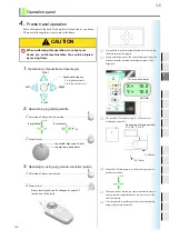
Page 28: ... start of embroidery 1 TURN ON THE POWER P 4 2 2 INPUT OF DESIGN DATA P 4 2 3 AUTO COLOR CHANGE AC AUTO START AS P 4 8 4 AUTO STITCH TYPE SELECTION P 4 9 5 PERFORM FRAME TRAVEL TO THE DESIGN START POSITION P 4 11 6 SETTING FOR THE NUMBER OF REVOLUTIONS P 4 12 7 CONFIRMATION OF HEAD TO USE P 4 13 8 START P 4 13 ...

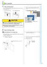
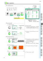
Page 29: ...t turn off the power The stored design data could be damaged Shape of power switch differs depending on model It takes a while until the screen switches to the main screen Award modular BIOS Press DEL to set up Now System Loading 40 Windows CE net Microsoft Now System Loading 40 Software version Turn ON the power switch Turn OFF the power switch When you input design data from memory this operatio...

Page 30: ...t this moment data is not set yet To perform data set proceed to the following operation When finishing operation here Main screen Other setting operation 2 Execution of data set The message for confirmation will be displayed 3 Set End When not executing to stop A A List screen 2 Data Input FD Press List screen or Cursor Code format G018 DSZ INDIAN 3843 File name Design name The number of stitches...

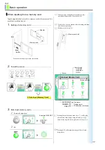
Page 31: ...l display the image of the selected design data When you input design data from memory this operation is unnecessary Proceed to p 4 6 Wait for five or more seconds after the setting and then start the next operation Memory card slot p 3 8 Memory card slot Eject button To take out the adapter press the eject button Slot Adapter Memory card List screen A 3 Data Input Memory Card Press List screen A ...

Page 32: ... is not set yet To perform data set proceed to the following operation When finishing operation here Main screen Other setting operation 2 Execution of data set The message for confirmation will be displayed 3 Set End When not executing to stop A G006 DST Coaster 5433 1 Data Input Memory The screen will switch E A D2 F1 F6 Are you ready A G006 DST Coaster 5433 Are you ready E JZ07 ...

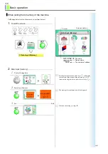
Page 33: ...f the design being selected p 6 2 To return to the original screen press the reset key 2 Execution of data set The message for confirmation will be displayed 3 Set End When not executing to stop List screen A 1 Data Input Memory Press Cursor G018 DSZ INDIAN 3843 File name Design name The number of stitches Screen number 1 Data Input Memory A G006 DST Coaster 5433 G006 DST Coaster 5433 Are you read...

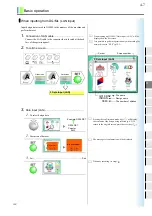
Page 34: ...sign being selected p 6 2 To return to the original screen press the reset key 2 Execution of data set The message for confirmation will be displayed 3 Set End When not executing to stop When starting up DG ML Data Input LAN will be displayed on the list screen It is possible to perform operation only when setting for network is set to YES p 12 2 Cursor G018 DSZ INDIAN 3843 File name Design name T...

Page 35: ...Main screen twice Other setting operation Automatic start 1 2 Automatic color change Same Color AS The machine will start automatically only when different colors are selected before and after color change The machine will start automatically even when the same color is selected before and after color change 1 2 1 Auto Color Change AC Auto Start AS List screen B 1 Auto Color Change AC Auto Start A...

Page 36: ... Color Change AC Auto Start AS To perform automatic color change and to start the machine automatically at embroidering set YES to Auto Color Change AC Auto Start AS p 4 8 The number of color change steps in design of which data is set will be displayed 6 steps in this example 1 2 1 a C0 Looper number Color scheme L loop C chain Needle height p 8 2 p 6 6 p 2 6 CM head 2 Auto Stitch Type Selection ...

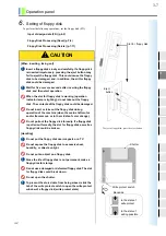
Page 37: ...itch type 9 Needle height End Switching the screen Main screen twice Other setting operation B 3 d C5 An example of selection B 3 d C6 An example of selection Continue the procedure An example of selection B f L 5 2 6 B An example of selection f C5 6 B f C7 An example of selection 6 E A D2 F1 F6 JZ07 ...

Page 38: ...vel 1 Operation by manual frame travel key s 2 Operation by jog dial jog shuttle 1 Selection of frame travel direction 2 Frame travel CAUTION When performing this operation do not put your hands etc on the machine table You could be injured by moving frame It is possible to perform manual frame travel only when the main screen is displayed Along with frame travel the current frame position the dis...

Page 39: ...ion When the LED lamp lights it will become possible to perform operation When you do not use the jog remote controller store it in a jog remote controller pocket etc not to move the frame carelessly Lit Frame travel speed can be changed by angle of inclination of the stick The number of revolutions will change automatically according to stitch length of design data with setting the value here as ...

Page 40: ...er checking the thread start the machine again CAUTION Before starting the machine pay enough attention to the surrounding safety Since the needle and or frame move you could be injured Do not put your hands etc on the machine table Since the frame moves you could be injured During stop Start switch Press and release immediately Operation starts Start switch Keep on pressing Start of inching opera...

Page 41: ...4 14 Basic operation ...

Page 42: ...ACK FORWARD COLOR CHANGE UNIT P 5 3 3 FRAME BACK FORWARD SPECIFICATION BY THE NUMBER OF STITCHES P 5 4 4 MANUAL COLOR CHANGE P 5 5 5 MANUAL THREAD TRIMMING P 5 5 6 REPEAT P 5 6 7 AUTOMATIC ORIGIN RETURN P 5 8 8 MANUAL OFFSET P 5 9 9 OFFSETTING AT AUTOMATIC COLOR CHANGE P 5 10 10 AUTOMATIC OFFSET P 5 12 11 TRACE P 5 14 12 SETTING FOR FRAME BACK FORWARD P 5 15 ...

Page 43: ...rame or needle moves to activate ATH you could be injured Frame back It makes only the frame move in the direction to which stitches return Up to the top of design at a maximum Frame forward It makes only the frame move in the direction to which stitches advance Up to the end of design at a maxi mum The value currently selected FB FF can be confirmed on the operation panel At thread breakage a val...

Page 44: ...he frame will move The machine will perform FB to the previous color change code in this example Switching the screen Main screen twice Other setting operation WARNING When performing frame back forward do not put your hands etc near the needle or on the machine table Since the frame or needle moves to activate ATH you could be injured Frame back It makes only the frame move in the direction to wh...

Page 45: ...ATH to trim thread and then the frame will move The machine will perform FB by 800 stitches in this example Switching the screen Main screen twice Other setting operation WARNING When performing frame back forward do not put your hands etc near the needle or on the machine table Since the frame or needle moves to activate ATH you could be injured Frame back It makes only the frame move in the dire...

Page 46: ...hands etc access to the looper case or tension base You could be injured by the moving looper case or tension base CAUTION When performing this operation do not put your hands etc near needle or on the machine table Since needle bar will move up down you could be injured The looper case and tension base will slide When performing this operation in the middle of embroi dery the machine will perform...

Page 47: ...n Repeat setting must be performed after inputting data The design of which data has been set is the target It is not possible to set repeat in the middle of embroi dery Outline of repeat p 5 7 List screen List screen Press B B 4 Repeat or Repeat mode 1 Usual repeat X axis mirror image repeat Y axis mirror image repeat 180 degrees rotated repeat To move to the next design after thread trimming To ...

Page 48: ...n interval amount in X direction 4 5 6 1 2 3 Priority to X 2 4 6 1 3 5 Priority to Y Direction of repeat is determined by Direction at design interval setting The left illustration is an example of repeat to minus direction in both X and Y no display no display Design start position Y X pb In X axis mirror repeat or Y axis mirror repeat the machine repeats design as the initial setting is in the n...

Page 49: ...eturn do not put your hands etc on the machine table at the end of embroidery Since the frame moves you could be injured pd Y X Design start position In 180 rotated repeat the machine repeats design as the initial setting is in the number of odd times and repeats the reversed design in the number of even numbered times in a sequential order 1 3 5 2 4 6 X Y Y priority 180 rotated repeat When automa...

Page 50: ...Other setting operation Outline of manual offset 1 Stop the machine at the free setting point A and perform manual thread trimming 2 Move the frame by manual frame travel to the front B for checking embroidery design etc CAUTION When performing this operation do not put your hands etc near needle or on the machine table Since the frame will move you could be injured List screen List screen Press D...

Page 51: ... press the SET Switching the screen Main screen Other setting operation CAUTION Do not put your hands etc on the machine table at color change in process of embroidery or at the end of embroidery Since the frame moves you could be injured Set offsetting at automatic color change on the screen of automatic embroidery mode selection p 4 9 Automatic offset must be set p 5 12 Even if automatic offset ...

Page 52: ...tinue 5 The machine will stop at the end position of design E to perform thread trimming and the embroidery frame will move to the offset start position A through the middle position B It is possible to perform this example when the following settings are set to to perform Automatic offset p 5 12 Automatic start p 4 8 Even if automatic offset is not set the frame will move at color change when off...

Page 53: ...nough attention to the surrounding safety and then start operation At the end of embroidery do not put your hands etc on the machine table Since the frame moves you could be injured Automatic offset must be set after inputting data The design of which data has been set is the target If data of another design is set the set value will be deleted Outline of automatic offset p 5 13 List screen List s...

Page 54: ...through the middle position B 3 When you change fabric and start the machine the embroidery frame will move to the start position of design C through the middle position B and embroidery will start It is possible to perform this example when the following settings are set to to perform Automatic start ATH If there is no middle position B the frame will not go through B Middle position OF1 C Start ...

Page 55: ... You could be injured by moving frame It is not possible to perform tracing in the middle of embroidery Outline of trace p 5 13 List screen List screen Press D1 D1 5 Trace or The current needle position will be displayed Frame travel speed Not to perform Low Low speed High High speed 1 2 D1 Low High Needle Position f 1 2 5 Trace Low Example Low speed E A D2 F1 F6 Offset start position 6 1 2 3 4 5 ...

Page 56: ... in which frame limit is not detected this example is not applied When tracing is interrupted When the machine is in the following factor the frame will return to the start point of trace when you perform Manual offset p 5 9 or Manual origin return p 6 3 Therefore perform tracing again according to need after moving the frame Stop by the bar switch or stop switch When the fix position signal does ...

Page 57: ...hing the screen Main screen twice Other setting operation To change feed unit 2 Change of feed unit 1 Select FF FB feed unit 2 Change feed unit End Switching the screen Main screen twice Other setting operation Example FF FF E A D2 F1 F6 Example Feed unit 3 Example 5 5 E A D2 F1 F6 JZ07 ...

Page 58: ...ely 1 CONFIRMATION OF DESIGN CONFIRMATION MODE P 6 2 2 MANUAL ORIGIN RETURN P 6 3 3 TOTAL STITCH COUNTER DESIGN TIME P 6 3 4 POWER RESUME P 6 4 5 CHECKING OF SOFTWARE VERSION P 6 4 6 PRESET HALT P 6 5 7 NEEDLE BAR COLOR P 6 6 8 AUTOMATIC START AFTER AUTOMATIC DATA SET P 6 7 9 SLEEP MODE P 6 7 ...

Page 59: ...parameter This shows the next page exists Pressing i key again will cause the next page to be displayed 3 Confirmation of error stack The code number occurred the lattermost is No 1 An example of code number 383 p 13 3 This shows the next page exists Pressing i key again will cause the next page to be displayed Step Offset 1 10 3 10 5 7 2 7 8 4 1 9 Fine stitch Coordinates Stitch counter Function S...

Page 60: ... set Switching the screen Main screen twice Other setting operation CAUTION When performing this operation do not put your hands etc near needle or on the machine table Since needle bar will move up down you could be injured Performing this operation in the middle of embroidery will cause the frame to move to the origin after thread trim ming When automatic offset is set the offset start position ...

Page 61: ...Since needle bar will move up down you could be injured If memory of frame origin is wrong it is not possible to move the frame correctly Correct frame travel is subject to correct memory of frame origin p 11 8 After power resume the machine will stop at the fixed position and it will be possible to continue the embroidery When operation of the machine is stopped and the power is turned on after t...

Page 62: ...fore end code 1D2 Halt for lubrication OIL When the machine stops a code number will be displayed At shipment of the machine only halt for lubrication 10 100 000 stitches is set It is not particularly necessary to change the value 6 Preset Halt 1 2 3 4 5 Stitch Data Design Lubrication Just before End Code When counting reaches the set number of stitches the machine will stop When counting reaches ...

Page 63: ...huttle Looper f The last looper 3 Color scheme 4 Set End To finish the working press and then press SET Main screen Other setting operation The number of selectable colors is 32 10 Needle Bar Color Looper No Color scheme Needle bar color pallet Cursor List screen List screen B Press B 10 Needle Bar Color or a 1 2 3 4 5 6 7 8 9 b c d e f Example red b a 1 2 3 4 5 6 7 8 9 b c d e f Continue the proc...

Page 64: ...ion 9 Sleep mode Keep on pressing the sleep mode key during stop of the machine in the state of the main screen The lamp will light in red and the power of the machine will be turned OFF The machine will be in a sleep mode during lighting of the lamp and it is not possible to operate the machine Pressing this key again will cancel the sleep mode NO The current setting value will be displayed List ...

Page 65: ...6 8 Convenient functions ...

Page 66: ...TA CONVERSION P 7 2 2 CLEANUP P 7 3 3 DATA EDIT MODIFY DELETE P 7 4 4 DATA EDIT INSERT P 7 6 5 FLOPPY DISK PROCESSING SAVE P 7 9 6 FLOPPY DISK PROCESSING DELETE P 7 11 7 MEMORY CARD PROCESSING SAVE P 7 12 8 MEMORY CARD PROCESSING DELETE P 7 13 9 DELETING MEMORY DESIGN P 7 14 10 INITIALIZATION OF MEMORY P 7 15 ...

Page 67: ... 4 Reversion End Switching the screen Main screen twice Other setting operation Outline of data conversion Set data conversion after data input It is not possible to perform setting for data conversion in process of embroidery List screen List screen B Press B 3 Data Conversion or To perform Not to perform p q 3 Data Conversion Crosswise X Reversion Rotating angle Lengthwise Y 150 Example 150 150 ...

Page 68: ...ion of stitch length to clean up In this example stitches of 0 6 mm or less are targets to clean up 4 Set Removed Stitches In this example the number of stitches of 0 6 mm or less is 35 CAUTION This operation will overwrite the original design data by design data after cleanup Therefore store the original design data into a floppy disk or memory card according to need p 7 9 p 7 12 It is not possib...

Page 69: ... To return to the original screen press the reset key 2 Set Stitch data Function code Stitch JUMP Jump STOP Stop HIGH High speed LOW Low speed ATH ATH SEQ Sequin CAUTION This operation will overwrite the original design data by design data after edit Therefore store the original design data into a floppy disk or memory card according to need p 7 9 p 7 12 Are you ready Are you ready E E A D2 F1 F6 ...

Page 70: ...le of embroidery only the current stitch and after can be searched Every pressing SET will cause stitch data that contains the same function code to be searched sequentially It is also possible to select other function codes by turning the jog dial When the selected function code does not exist display will not change 4 Completion of selection 4 Select Modify or Delete To delete stitch data press ...

Page 71: ...een Main screen Other setting operation 4 Data edit insert Insert a stitch data to the design data that is stored in the memory 1 To call the screen CAUTION This operation will overwrite the original design data by design data after edit Therefore store the original design data into a floppy disk or memory card according to need p 7 9 p 7 12 12 Example 12 mm Example stitch 101 40 50 JUMP Are you r...

Page 72: ...itch JUMP Jump STOP Stop HIGH High speed LOW Low speed ATH ATH SEQ Sequin 3 Select the stitch data When not using search function 1 Select the stitch Contents of data of the 100th stitch 2 Proceed to 4 of When using search function 1 Movement of the cursor Display frame of function code 2 Select the function code G006 DST Coaster 5433 G006 DST Coaster 5433 1 9 9 X Function code Y Stitch number 2 1...

Page 73: ...d sequentially It is also possible to select other function codes by turning the jog dial When the selected function code does not exist display will not change 4 Completion of selection 4 Select Insert 5 Set When not executing to stop Inserting data it is inserted before the selected stitch data 6 Select Modify 7 Modify an X data 8 Modify a Y data Example 100th stitch 100 Α Insert Example insert ...

Page 74: ...ill be displayed 11 Set End When not executing to stop Switching the screen Main screen Other setting operation 5 Floppy disk processing Save Write design data memory design stored in the memory into a floppy disk FD 1 Set the floppy disk 2 Input the password Example Jump JUMP 101 40 50 JUMP Are you ready E E A D2 F1 F6 It is necessary to input a password p 11 9 1 Floppy Disk Processing Save Setti...

Page 75: ...ssing the reset key 3 Write memory design into a floppy disk 1 Select a memory design Pressing the confirmation mode key will display the contents of the design being selected p 6 2 To return to the original screen press the reset key 2 Set The message for confirmation will be displayed 3 Set End When not executing to stop Switching the screen Main screen twice Other setting operation M Example M ...

Page 76: ...ing selected p 6 2 To return to the original screen press the reset key 2 Set An image of design will be displayed 3 Set The message for confirmation will be displayed 4 Set End When not executing to stop Switching the screen Main screen twice Other setting operation List screen List screen 2 Floppy Disk Processing Delete or Press Cursor 2 Floppy Disk Processing Delete Z T B Z T T G006 DST Coaster...

Page 77: ...e remaining password Input a password up to the fourth digit in the same manner 3 Decide the password When the password is wrong code number 2C7 will be displayed Input the password again after pressing the reset key It is necessary to input a password p 11 9 4 Memory Card Processing Save Setting range 4 to 8 digits Password will be displayed with Only capital letters of English characters can be ...

Page 78: ...ion will be displayed 3 Set End When not executing to stop Switching the screen Main screen twice Other setting operation 8 Memory card processing Delete Delete design data memory card design stored in a memory card by one design unit 1 Set the memory card 2 To call the screen G006 DST Coaster 5433 G006 DST Coaster 5433 Are you ready A G006 DST Coaster 5433 Are you ready G006 DST Coaster 5433 E E ...

Page 79: ... setting operation 9 Deleting memory design Delete design data registered in the memory 1 To call the screen 2 Deleting memory design 1 Select a deleting method Z T B Z T T G006 DST Coaster 5433 T G006 DST Coaster 5433 G006 DST Coaster 5433 Are you ready G006 DST Coaster 5433 Are you ready E E A D2 F1 F6 To delete design data stored in a floppy disk p 7 11 To delete design data stored in a memory ...

Page 80: ...machine to become the following status 1 All the memory designs will be erased 2 Each setting value will return the initial value p 11 11 3 The password will return to the initial value p 11 9 CAUTION Before installing the software write design data that is currently stored in the memory to a floppy disk or a memory card p 7 9 p 7 12 Design data could be damaged by unexpected cause To turn on the ...

Page 81: ...etting For details consult the distributor Installation of software Each setting value will return to the initial value p 11 11 The password will return to 0000 Initialization of memory p 7 15 Each setting value will return to the initial value p 11 11 The password will return to 0000 All memory designs will be erased 1 2 3 2 3 Install An example when using a floppy disk It is also possible to use...

Page 82: ...10 11 12 13 14 15 To operate the machine manually Activate the machine manually 1 MANUAL NEEDLE HEIGHT SELECTION P 8 2 2 MANUAL STITCH TYPE SELECTION P 8 2 3 D AXIS ORIGIN RETURN P 8 3 4 LOOPER FIXED POSITION RETURN P 8 4 ...

Page 83: ...or on the machine table Since needle bar moves up and down you could be injured To perform embroidery with the selected needle height excluding H set NO to Auto Color Change AC p 4 8 Needle height 0 9 times H retracting Low High position F5 List screen List screen 2 Manual Needle Height or Press F5 The needle height that is currently selected will be dis played 0 2 mm to 9 4 7 mm In increments of ...

Page 84: ...ching the screen Main screen Other setting operation CAUTION When performing this operation do not put your hands etc near to needle Since sewing needle rotates you could be injured D axis origin In the state that hook section of sewing needle faces to the front Looper origin In the state where the threading hole 2 of the looper 1 is positioned at the rear side At this moment it is possible to per...

Page 85: ...ion Looper fixed position In the state where the threading hole 2 of the looper 1 is positioned at the front side At this moment it is possible to perform threading from the threading hole 4 of the needle plate 3 In case of stop by bar switch also including start stop switch or by thread breakage the looper will return to the fixed position automatically 1 2 3 4 Viewing from top Fixed position 3 4...

Page 86: ... 9 10 11 12 13 14 15 Parameter rpm frame drive Set working conditions of the machine 1 FRAME TRAVEL SPEED P 9 2 2 MAX REVOLUTION P 9 2 3 FRAME TYPE P 9 3 4 FRAME DRIVE START TIMING P 9 3 5 LIMIT OF MAX REVOLUTION P 9 4 ...

Page 87: ...1 To call the screen 2 To set End Switching the screen Main screen twice Other setting operation 200 mm sec Setting range 100 200 mm sec F2 List screen List screen 5 Frame Travel Speed or Press F2 Example 100 mm sec 200 100 E A D2 F1 F6 The number of revolutions will vary automatically depending on stitch length of design data It is not possible to set this value exceeding Max Revolution Limit p 9...

Page 88: ...ain screen twice Other setting operation At present setting is applied only to Border frame It is not possible to change the contents of setting Border Border frame List screen List screen C Press 7 Frame Type or C E A D2 F1 F6 This setting adjusts thread tension finishing of sewing Start operation from the main screen F2 List screen List screen 2 Frame Start Timing or F2 2 Frame Start Timing Sett...

Page 89: ...r 2C7 will be displayed Input the password again after pressing the reset key 2 To set End Switching the screen Main screen twice Other setting operation Max revolution It is not possible to increase Max Revolution p 9 2 higher than the value set here It is necessary to input a password p 11 9 Start operation from the main screen List screen 1 Max Revolution Limit F2 1 Max Revolution Limit Setting...

Page 90: ... 15 Parameter embroidery head Set working conditions of the machine 1 WEAK BRAKE P 10 2 2 THREAD BREAKAGE DETECTION P 10 2 3 THREAD MANAGEMENT AFTER THREAD TRIMMING P 10 3 4 THE NUMBER OF TIE STITCHES P 10 3 5 FRAME BACK FUNCTION P 10 4 ...

Page 91: ...ng operation Use this function when releasing the main shaft brake in such a case as maintenance Start operation from the main screen F3 List screen List screen 2 Weak Brake or F3 YES Setting range YES To apply brake NO not to apply brake YES is automatically set at start of the machine Example NO YES NO E A D2 F1 F6 F2 List screen List screen 7 Thread Breakage Detection CM or Press F2 F2 0 10 3 7...

Page 92: ...t design inter val movement the next stitch is generated by remaining cut end of thread and thread to start to sew after color change F5 List screen List screen 7 Thread Management After Trimming CM or Press F5 Down Setting range Down To push thread under the fabric Up1 To pull thread on the fabric Up2 To pull thread on the fabric and take off thread from the needle Example to pull out thread onto...

Page 93: ...activates to trim sewing thread the machine will perform frame back To perform embroidery from the position where frame back started without detection of thread breakage set the turn over switch of the head to Top once after performing frame back F5 List screen List screen 9 Frame Back Function CM or Press F5 All Setting range All Embroidery will start after frame back NO Not to perform frame back...

Page 94: ...setting p 11 6 to p 11 11 after installation of software 1 INSTALLATION OF SOFTWARE IN CASE OF FLOPPY DISK P 11 2 2 INSTALLATION OF SOFTWARE IN CASE OF MEMORY CARD P 11 4 3 LANGUAGE P 11 6 4 MACHINE TYPE P 11 7 5 FRAME ORIGIN MEMORY P 11 8 6 SETTING FOR PASSWORD P 11 9 7 SETTING FOR EACH SETTING ITEM PARAMETER P 11 11 ...

Page 95: ... 11 8 Important Six pieces of floppy disk DISK 1 6 to DISK 6 6 for installation of software are packed with the machine The latest software at the shipment of the machine is stored in these floppy disks Regarding the latest version and how to obtain it please ask the distributor for information It is also possible to install the software from the mem ory card p 11 4 TCMX Ver DISK 1 6 System Progra...

Page 96: ...allation Wait for a while 4 Change the floppy disk Take out the DISK 2 6 and insert the DISK 3 6 5 Set Wait for a while Insert up to DISK 6 6 in the same manner 6 Take out the floppy disk Installation Install DISK 2 6 Insert Disk 2 6 into FDD Push SET key Now Installing Installing DISK 3 6 Insert Disk 3 6 into FDD Push SET key Now Installing Installing Continue the procedure Finish Completion DISK...

Page 97: ... according to the following procedure 1 To call the screen 1 Turn OFF the power 2 Insert the adapter and memory card CAUTION Before installing the software write design data that is currently stored in the memory to a floppy disk or a memory card p 7 9 p 7 12 Design data could be damaged by unexpected cause To turn on the power again wait for five seconds or more If not the software could be damag...

Page 98: ... the adapter and memory card 1 IP setting For details consult the distributor Installation of software Each setting value will return to the initial value p 11 11 The password will return to 0000 Initialization of memory p 7 15 Each setting value will return to the initial value p 11 11 The password will return to 0000 All memory designs will be erased 1 2 3 2 3 Install Installation Install Now In...

Page 99: ... set End 3 Set Machine type continuously p 11 7 Wait for a while After installation of software English will become the initial value When the language you use is English this setting is unnecessary Setting range English French German Italian Spanish Czech Por tuguese Japanese Chinese English F4 List screen List screen 10 Language or When turning ON the power after installation of software the lis...

Page 100: ...ed after installation of software this setting is necessary After the setting turn OFF ON the power When turning OFF ON the power wait for five or more seconds Neglect of this operation could cause malfunctioning of the machine 3 Machine Type SET F4 Machine Name S Only Machine Name is displayed Even if the same spec as the machine is registered after installation of software press SET to decide th...

Page 101: ...1 CAUTION Do not perform this operation in the middle of embroidery It is not possible to operate manual offset or manual origin return after moving to the origin it will become impossible to continue the embroidery When performing this operation do not put your hands etc on the machine table You could be injured by moving frame Frame origin memory is already set at the shipment of the machine If ...

Page 102: ...y 4 Fourth character The third character 0 will be replaced with for display 5 Decide the password The fourth character 0 will be replaced with for display When the password is wrong code number 2C7 will be displayed Input the password again after pressing the reset key The password is set to 0000 at the shipment of the machine Call the main screen and then start operation When you perform install...

Page 103: ...de the password The fourth character K will be replaced with for display 4 Input again 1 First character Input the new password again for confirmation In this example 2R5K is applied It will switch to Input characters to the fourth digit in the same manner 2 Decide the password End The fourth character K will be replaced with for display Switching the screen Main screen twice Other setting operati...

Page 104: ... needle height selection 9 Automatic start after automatic data set The number of tie stitches 2 Max Revolution CM 800 Thread handling after thread trimming Down Frame back forward F B Setting for frame back function NO Frame back forward feed unit 1 Taping CM NO Frame Back All Head Sew 0 Password 0000 Halt Frame Back NO Limit of max revolution 800 Preset halt stitch 0 Frame drive start timing 280...

Page 105: ...11 12 Software installation and necessary ...

Page 106: ...12 1 2 3 4 5 6 7 8 9 10 11 12 13 14 15 Setting for option These settings make each option available for use 1 TAPING CM HEAD P 12 2 2 NETWORK P 12 2 ...

Page 107: ...sible 1 To call the screen 2 To set Switching the screen Main screen Other setting operation It is not possible to perform setting for taping in the middle of embroidery NO F5 List screen List screen 10 Taping CM or Press F5 Example to use NO YES E A D2 F1 F6 Call the main screen and then start operation F3 List screen List screen 10 Network or F3 YES to perform networking NO not to perform networ...

Page 108: ...13 1 2 3 4 5 6 7 8 9 10 11 12 13 14 15 Troubleshooting How to cope with troubles is described 1 COPING WITH ERROR CODE P 13 2 2 USUAL STOP FACTOR P 13 4 3 THE MACHINE DOES NOT WORK NORMALLY P 13 5 ...

Page 109: ...n H retracting position of Z axis at CM head Set needle height to H 281 The target needle position is not detected even after 15 seconds from start of color change at FM head Return the needle position so that it becomes the correct display Adjust or replace the potentiometer needle position sensor 291 The machine detected thread breakage Check the thread Tension base card is faulty Replace the te...

Page 110: ...tation of X axis driver Turn OFF ON the power Check connection of motor of each frame driver and sensor wire Replace the corresponding frame driver Replace the corresponding frame motor 32B The machine cannot memorize excitation of Y axis driver 331 Bobbin changer error Operate the bobbin changer manually to check the place where movements are bad and adjust it 382 The needle position signal statu...

Page 111: ...the FDD connector If there is no problem with the connection replace the FDD unit No Stop Factor Corrective Action 1B1 Stop due to a frame stepping code In this case it is not stop by abnormality Perform Start operation or Frame back forward operation or press any operation key excluding manual frame travel key to continue operation of the machine 1B2 Stop due to a stop code 1B3 Stop due to stop c...

Page 112: ...le position is properly indicated in the manual color change section on the operation panel Thread detection error Malfunctioning of rotary tension disk or rotary disk slit Clean rotary tension disk or rotary disk slit and check movement Jump error Incorrect positioning of parts related to needle bar drive system Adjust fixing position of upper dead point stopper Design displaced Incorrect tension...

Page 113: ...rame drive belt Adjust the belt tension Malfunctioning of frame drive system Replace adjust the parts Overall frame weight is excessive Lower the r p m of the main shaft Driver X Y axis defective Replace the X axis Y axis drivers Thread breakage Wrong needle rotary hook timing or improper gap Adjust the timing or gap Wrong needle bar lower dead point Readjust the lower dead point Scratches on rota...

Page 114: ...14 1 2 3 4 5 6 7 8 9 10 11 12 13 14 15 Maintenance Periodical maintenance is necessary 1 WARNING P 14 2 2 CLEANING P 14 2 3 LUBRICATION P 14 3 4 GREASING P 14 4 5 INSPECTION P 14 5 6 REPAIR P 14 5 ...

Page 115: ...ervals Although each card of the machine has a backup battery data may be lost for about one month because voltage of the battery will come down gradually due to discharge when the power switch is turned off Assure enough illumination Assure 300 lux or more for working areas including underneath part of the machine table when changing under threads or performing daily maintenance Before operating ...

Page 116: ... machine which results in serious injury CAUTION When performing lubrication use Tajima s genuine TF oil When using other oil than this by necessity select 150 spindle oil ISO viscosity grade VG18 Lubricating spot Cycle Each drive lever 1 each sleeve 2 connecting rod 3 slide block 4 connecting block 5 needle bar 6 Once week 2 1 2 4 1 1 3 2 2 4 5 6 2 JZ07 ...

Page 117: ...be caught by the machine which results in serious injury CAUTION When performing greasing consult the distributor Use the recommended goods mineral oil based lithium grease or equivalent Greasing spot Cycle Drive cam 1 positioning cam 2 each gear 3 knife drive rack 4 Once 3 months 1 2 3 3 4 3 3 3 1 1 JZ07 ...

Page 118: ...ths Belts of X Y drive system Rotating and sliding part Degree of wear WARNING Before working be sure to turn off the primary power supply Before turning off the primary power supply turn off the power switch Even if the primary power supply is turned off some circuits are still charged Wait 4 minutes until these circuits are completely discharged and then start working If the machine needs repair...

Page 119: ...14 6 Maintenance ...

Page 120: ...refer to each documentation 1 TERMINOLOGY P 15 2 2 AMBIENT NOISE LEVEL P 15 7 3 POWER SUPPLY SPECIFICATIONS P 15 7 4 SELECTING NEEDLE FOR CHENILLE EMBROIDERY P 15 8 5 COMBINATION OF CHENILLE EMBROIDERY NEEDLE NIPPLE AND NEEDLE PLATE P 15 8 6 ELECTRICAL SYSTEM DIAGRAM P 15 9 ...

Page 121: ...t output of data C CAP FRAME A kind of embroidery frames for embroidery on cap There are two types of cap frame One is wide cap frame another is semi wide cap frame The wide cap frame can embroider wider area of circumference directions compared with the semi wide cap CHECK SUM A kind of measures to detect error of data transfer or saved memory contents CLEANUP To make preceding and succeeding sti...

Page 122: ...eset head pitch head interval FIXED POSITION It is the regular stop position and is indicated by angle of the main shaft of the machine FLOPPY DISK An external memory device of which round shaped polyester surface is pasted with magnetic powder It is used for storing design data etc FLOPPY DISK DRIVE A device to write or read data or program of floppy disk FRAME BACK To move the embroidery frame o...

Page 123: ...ed with a floppy disk MEMORY DESIGN Design data that is written in the memory MEMORY Internal memory device MEMORY REGISTRATION To write to memory memory writing MEMORY WRITING To write to memory memory registration N NEEDLE BAR SELECTION To set orders of needle bars to be used NIPPLE Part to press material to be embroidered in LH head Attachment suitable for material to be sewn such as cord tape ...

Page 124: ...OF STITCHES The number of needle sticks when embroidering TIE STITCHING It means stitching that prevents fray of thread It is executed at thread trimming TUBULAR GOODS FRAME A kind of embroidery frames It mainly holds trainer T shirt etc to be stretched U UBC Abbreviation of Under thread Bobbin Changer Refer to BOBBIN CHANGER UNDER THREAD RELEASE Action that makes the frame perform slight reciproc...

Page 125: ...lemental documentation Z Z AXIS Driving shaft to change needle height TCMX series ZIGZAG SWING EMBROIDERY To sew cord shaped material by zigzag swing Needle are not located to cord shaped material generally JZ07 ...

Page 126: ...volutions of the machine 5 Measuring tool Conformity to IEC61672 1 2002 Class 1 3 Power supply specifications Since power spec of the machine is specified clearly as shown below use the machine under these conditions VOLTAGE ALLOWABLE VOLTAGE RANGE Within 10 of the rated voltage POWER CONSUMPTION MAX 140W 180VA FREQUENCY 50 60Hz INSULATION RESISTANCE 10M ohms or more at 500 V megger WARNING Since ...

Page 127: ...le to per form chain stitching with such material as felt with which fuzzing is hard to occur Chain stitching only Loop stitching is not suitable Suitable fabric Felt Thin material fine knit CAUTION In chenille embroidery if combination of needle nipple needle plate and thread is not proper problems will occur in finishing When changing needle change combination referring to the list below Needle ...

Page 128: ... motor Head switch card CN3 CN1 Head card CN3 CN8 CN1 CN2 CN31 CN1 CN7 CN12 CN3 CN3 I F connector CN15 CN2 CN4 CN17 PC card slot FDD Origin sensor CN2 CN1 X axis sensor Main shaft motor CN2 CN6 Main shaft sensor CN14 Tension release motor Tension release potentiometer Color change potentiometer CN5 Electro magnetic counter CN12 CN2 CN4 CN5 CN13 Z axis motor Z axis potentiometer Looper motor CN16 C...

Page 129: ...15 10 Supplemental documentation ...

Page 130: ...ibited Manufactured by Tokai Industrial Sewing Machine Co Ltd NO 1800 Ushiyama cho Kasugai Aichi pre 486 0901 Japan Telephone 568 33 1161 Fax 568 33 1191 Distributed by Tajima Industries Ltd 19 22 Shirakabe 3 chome Higashi ku Nagoya 461 0011 Japan Telephone 52 932 3444 Fax 52 932 2457 Authorized Distributor ...

Reviews: