


Description Of Specific Functions
155
V260 Series High Performance Closed-Loop Vector Inverter User Manual
F5.3.33 DC injection braking intensity
Setting range: 30~120%
Factory default:
☆
This parameter defines the increased amplitude of motor magnetic flow when magnetic flow braking,
selected value is the relevant percentage of rated magnetic flow.
F5.3.34 Voltage over modulation
Setting range: 0, 1
Factory default: 1
Voltage over modulation refers to that in condition of lasting low grid voltage or lasting heavy load operation,
frequency inverter improve the output voltage with improving the utilization rate of its bus voltage. When over
modulation function is valid, output current harmonic will increase slightly.
0: Void
1: Effective
F5.3.35 Use ratio of dynamic braking
Setting range: 50~100%
Factory default: 100
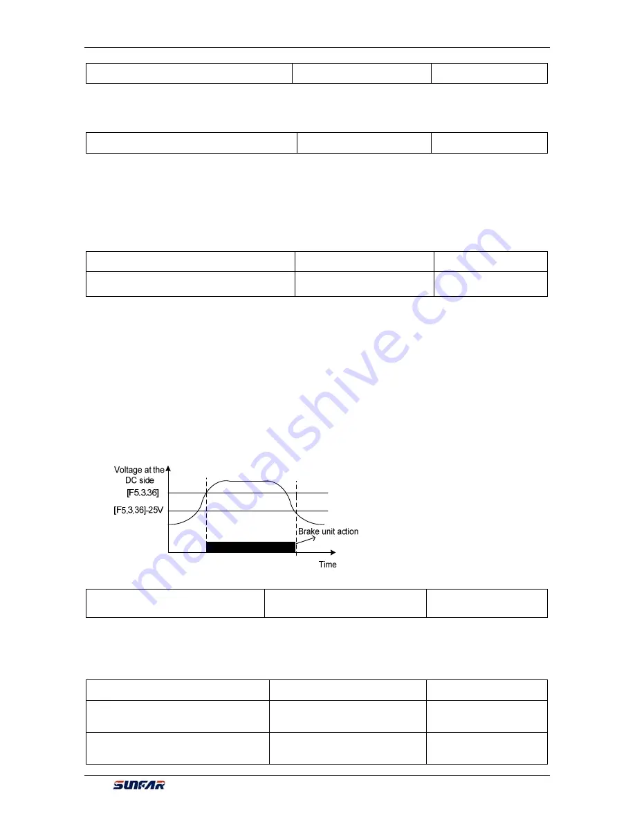
F5.3.36 Level of dynamic braking
starting action
Setting range: 700~760V
Factory default: 720
These two parameters is valid to frequency inverters with built-in braking unit (
22KW
and models below),
used to define action parameters of built-in braking unit of frequency inverters. When the voltage at internal
direct current side of frequency inverter is higher than starting action level of dynamic braking
[
F5.3.36
], build
in braking unit action. If there is external braking resistor, it shall make the direct current voltage fall back, via
releasing pumped-up voltage energy with braking resistor. When the voltage at DC side drops down to a
specific value, the built-in braking unit of the frequency inverter closes, as shown in Figure 7-44.
Utilization rate of dynamic braking is used to define the average voltage value forced on braking resistor of
braking unit action. Voltage on braking resistor is pulse width modulation wave. Duty ratio equals to action
ratio of dynamic braking. The large the action ratio is, the faster energy releases, and the more obvious the
effect is, as well as the larger power consumed on braking resistor is. Operator may consider setting the
parameters comprehensively according to the resistance of braking resistor, power and required braking
effect.
F5.3.37 Vibration suppression
coefficient
Setting range: 0.0; 0.1~10.00
Factory default: 0.0
Only valid with V/F control method. Selecting this parameter can restrain the output current oscillation.
Setting 0.0 to close this function. The larger the value is, the slower restraining action is and the wider the
biggest adjustment range is.
F5.3.38 Load balancing feature
Setting range: 0, 1, 2
Factory default:0
F5.3.39 Load balancing reference
Setting range: 0~5
Factory default:0
F5.3.40 Reference value for load
balance load
Setting range: 0.0~200.0%
Factory default:100.0
Figure 7-44 Dynamic braking


