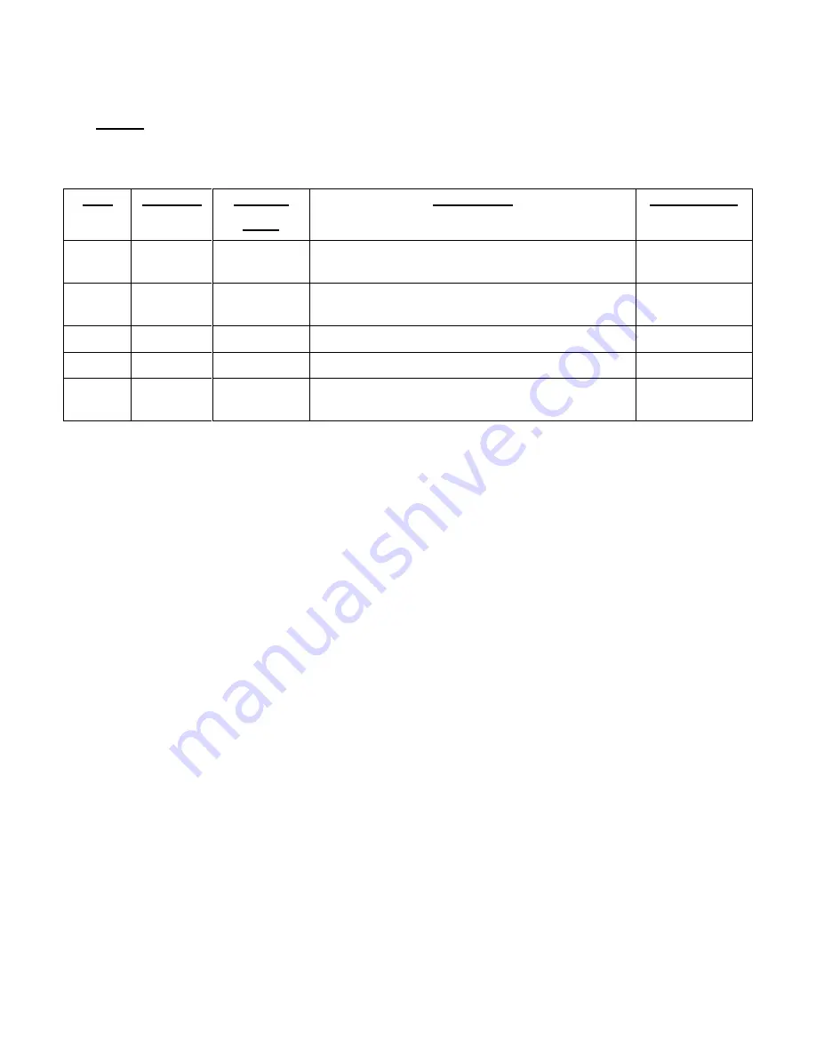
background image

Parts 


66


Cables 

The following cables are available for use with the HC-4A Series Compressors as accessories 
from SCAI. 
 

Item 

Quantity 

For Use 

With: 

Description 

Part Number 

HC-4A/ 

HC-4A2 

Accessory cable for remote On/Off,  
6 m (20 ft.) long. 

263887B20 

HC-4A 

Cold head cable, DE202/204SL, 3.3 m  
(11 ft.) long 

263941B11 

HC-4A 

Cold head cable, M204S, 3.3 m (11 ft.) long 

264187B11 

HC-4A 

Cold head cable, CH204S, 3 m (10 ft.) long 

267285C11 

HC-4A2 

Cold head cable, RDK-101, 3.3 m  (11 ft.) long 

268094C11 


Summary of Contents for HC-4A

Page 1: ...HC 4A and HC 4A2 Zephyr Air Cooled Helium Compressors Technical Manual Sumitomo SHI Cryogenics of America Inc 1833 Vultee Street Allentown PA 18103 4783 U S A Revision C May 2014 267825A ...

Page 2: ......

Page 3: ...nmental Requirements 19 Protective Earth Terminal 19 Maintenance Intervals 19 Installation Adapter Fitting 19 Adapter Fittings Optional Accessory 19 Remote On Off Cable Optional Accessory 20 Supplier Name and Address 20 Regulatory Compliance 20 INSTALLATION 21 Introduction 21 Receipt Inspection Instructions 21 Compressor Position 23 Mains Power Supply Connection 23 Field Wire the Compressor 25 Com...

Page 4: ...ce Checks 49 Current Measurement 50 Fan and Circulator 51 Winding Continuity Grounding and Resistance Checks Fan and Circulator Motors 51 PARTS 59 Ordering 59 Compressor Parts Identification and Numbers 59 Adapter Fittings 65 Cables 66 ILLUSTRATIONS LIST Figure 1 HC 4A Zephyr Series Flow Diagram 9 Figure 2 HC 4A Zephyr Outline Dimensions and Parts Identification 13 Figure 3 HC 4A2 Zephyr Outline D...

Page 5: ...ematic Air Cooled Unit 58 Figure 14 Parts Identification 61 Figure 15 Parts Identification for HC 4A 62 Figure 16 Parts Identification for HC 4A2 63 Figure 17 Parts Identification 64 Figure 18 Adapter Fitting 8F and 8M with Valve 65 Figure 19 Adapter Fitting 8F with Valve 65 TABLES Table 1 Terminal Position for Mains Power Supply 24 SJM P N 267825A ...

Page 6: ...iv This page is intentionally blank ...

Page 7: ...are used in this technical manual They appear as follows and serve the purposes stated WARNINGS call attention to actions or conditions that can result in serious injury or death to personnel CAUTIONS call attention to actions or conditions that can result in damage to the equipment or in abnormal performance NOTE NOTES give important additional information explanations or recommendations related ...

Page 8: ...essure as the gas warms Material failure and uncontrolled pressure release can cause injury Use two wrenches when disconnecting a gas line coupling to avoid loosening the cold head or compressor coupling Gas pressure can project the coupling with enough force to cause serious injury The compressor is charged with helium gas Vent both supply and return Aeroquip couplings to atmospheric pressure bef...

Page 9: ...e return coupling Reversed flow can contaminate the system with compressor oil A leaking coupling on an adsorber should not be repaired in the field Consult a Service Center Venting the adsorber will introduce contaminants to the system which cannot be removed in the field PREVENT EQUIPMENT DAMAGE Damage to gas lines can result from crimping by repeated bending and repositioning Never pull a vacuu...

Page 10: ...4 This page is intentionally blank ...

Page 11: ...RG21 6YT United Kingdom TEL 44 1256 853333 FAX 44 1256 471507 Sumitomo SHI Cryogenics of Europe GmbH Daimlerweg 5a D 64293 Darmstadt Germany TEL 49 6151 860 610 FAX 49 6151 800 252 Asia Sumitomo Heavy Industries Ltd Service Section Cryogenics Division 2 1 1 Yato Cho Nishitokyo City Tokyo 188 8585 Japan TEL 81 424 68 4265 FAX 81 424 68 4462 Sumitomo SHI Cryogenics Korea Co Ltd Room 619 620 Venture ...

Page 12: ...6 This page is intentionally blank ...

Page 13: ...cle cryogenic refrigeration system The information in this manual pertains only to the HC 4A Zephyr Series Compressors Other components used to form an operating system are described in separate technical manuals Pressures are stated as gauge not absolute Psig is pounds per square inch gauge and kPa is Kilopascals gauge kPa 6 895 x Psig Definition of Symbols used in this manual and on equipment Po...

Page 14: ...8 This page is intentionally blank ...

Page 15: ...2 Oil Injection Orifice 13 Gas Supply Coupling 3 Heat Exchanger 14 Gas Return Coupling 4 Compressor Capsule 15 Temperature Switches oil gas and compressor shell 5 Oil Separator 16 Internal Relief Valve 6 Oil Capillary Filter 17 Helium Pressure Relief Valve 7 Oil Capillary 18 Coolant Pressure Relief Valve 8 Adsorber 19 Circulator 9 Internal By pass Orifice 20 Accumulator 10 Surge Bottle 21 Air Heat...

Page 16: ...passes over the motor windings The second stage is in the oil separator whose element collects oil mist from the gas oil is agglomerated and returned to the compressor The third stage is the adsorber that removes any remaining oil the gas is carrying Oil collected in the separator flows back to the compressor through a capillary tube The differential gas pressure across the system is the moving fo...

Page 17: ... the compressor to the cold head The HC 4A compressor can be supplied with cold head cables for operating a DE 202 DE 204SL M204S or CH204S Cold Head The HC 4A2 compressor can be supplied with a cold head cable for operating an RDK 101 series cold head Compressor Power Cord Terminating with a 3 prong NEMA L6 20P plug the power cord supplies electrical power to the compressor Elapsed Time Meter The...

Page 18: ...FU8 1 0 AT 1 0 AT Fan and Circulator Inside Fan Cabinet FU9 0 63 AT 0 63 AT Fan and Circulator Inside Fan Cabinet Gas Supply and Return Couplings Both are self sealing size 8 male Aeroquip bulkhead couplings and are the points of connection on the front panel for the rest of the system Power On Off Switch This on off rocker switch starts and stops the compressor The switch lights to indicate that ...

Page 19: ...ption 13 Figure 2 HC 4A Zephyr Outline Dimensions and Parts Identification Dimensions in mm NOTE Three 3 8 mm holes at the bottom of the front panel may be used for bolts to prevent movement of the compressor ...

Page 20: ...tion 14 Figure 3 HC 4A2 Zephyr Outline Dimensions and Parts Identification Dimensions in mm NOTE Three 3 8 mm holes at the bottom of the front panel may be used for bolts to prevent movement of the compressor ...

Page 21: ...t an unsafe pressure Fan Moves room air through the air heat exchanger Gas Equalization Solenoid Valve This solenoid valve opens when the compressor is stopped The valve allows the helium gas pressure across the compressor to equalize to prevent oil from being blown out of the compressor into the low pressure return gas line Gas High Temperature Switch Located on the supply gas line near the top o...

Page 22: ...oil separator serves as a sump A cartridge above the sump contains fibrous material that acts as the separating agent Entrained oil coalesces on it forming large droplets that drain into the sump This unit needs no servicing or replacement Shell High Temperature Switch Located on top of the compressor next to the compressor motor terminals the switch opens at 80º C 176º F and stops the compressor ...

Page 23: ...ection on Mains Power Supply Connection Power required 3 4 kW 16 0 amperes full load at 220 V 60 Hz and 3 0 kW 15 5 amperes full load at 200 V 50 Hz 60 amperes starting current 73 amperes locked rotor current Power Cord Connector NEMA L6 20P 2 pole 3 wire 20 A 250 V male plug to connect to customer s receptacle Power Conductor Requirements for hard wiring if not using the compressor power cord Use...

Page 24: ... Compressor Only 1860 1900 kPa 270 275 psig 2070 2210 kPa 300 320 psig HC 4A with CH 202 Cold Head 1790 1830 kPa 260 265 psig 1930 2070 kPa 280 300 psig HC 4A with CH 204S Cold Head 1860 1900 kPa 270 275 psig 2000 2140 kPa 290 310 psig HC 4A2 with RDK 101 and ø x 20 ft flex gas lines 1655 1670 kPa 240 245 psig 1860 2210 kPa 270 320 psig HC 4A2 with RDK 101 and ø x 20 ft and 66 ft flex gas lines 14...

Page 25: ... when operating Mounting Position Compressor must be mounted base down and level within 5 degrees of horizontal Environmental Requirements Operating Environment Storage Ambient Temperature 4 C to 32 C 23 C to 65 C 40 F to 90 F 10 F to 149 F Magnetic Field Limits Compressor 150 gauss NOTE Operating the equipment out of specifications may void the warranty Equipment is designed for indoor use only P...

Page 26: ...Compliance Declaration of Conformity HC 4A Series Compressor Manufacturer s Name Sumitomo SCAI Cryogenics of America Manufacturer s Address 1833 Vultee Street Allentown PA 18103 U S A Authorized Representative s Name Sumitomo SHI Cryogenics of Europe Limited Authorized Representative s Address 3 Hamilton Close Houndmills Industrial Estate Basingstoke Hants RG21 6YT England Type of Equipment Cryoge...

Page 27: ...AMAGE Remove the shipping bolt retaining the compressor motor before running the compressor AVOID CONTAMINATION When checking the compressor for shipping damage do not connect gas lines and cold head The components may become contaminated with compressor oil AVOID EQUIPMENT FAILURE CONTAMINATION OR NUISANCE SHUTDOWN Do not tip the compressor more than 5 degrees from horizontal to avoid flowing oil...

Page 28: ...N Tell sensor turns blue in the arrow as shown below Proceed to either Step 5 1 or 5 2 Non Activated Good Activated Not Good AVOID ELECTRIC SHOCK All electrical supply equipment must meet applicable codes and be installed by qualified personnel AVOID ELECTRIC SHOCK Permit only qualified electrical technicians to open electrical enclosures to perform electrical checks or to perform tests with the p...

Page 29: ...CE SHUTDOWN Do not tip the compressor greater than 5 degrees from horizontal to avoid flowing oil into unwanted places and causing a nuisance shutdown The compressor must be installed base down within 5 degrees of horizontal and preferably at a height convenient for making connections and reading the pressure gauge Be sure the compressor cannot inadvertently roll from its location particularly if ...

Page 30: ...terminal positions for connecting the mains power supply cable 4 If required move the mains power supply wires to the correct terminal positions determined from Table 1 and tighten to 1 3 N m 11 5 in lb torque See Figure 4 Compressor Electrical Variation Incoming Power Terminal Position Hz Volts 1526G 60 220 L1 L2 50 200 L1 L2 50 220 L3 L4 1626G 60 220 L1 L2 50 200 L1 L2 50 230 240 L3 L4 26G 60 22...

Page 31: ...elief on the front panel Use one wrench to hold the strain relief body and one to turn the nut 3 Remove the field wiring access cover on the front panel to gain access to the terminal block 4 With a flat blade screwdriver loosen the power cord terminal screws and the ground connection Remove the two hot leads and ground 5 Remove the complete power cord Instructions for field wiring follow Use 12 A...

Page 32: ...le by tightening the cap of the strain relief fitting Use two wrenches to prevent turning the body of the strain relief fitting 4 Reinstall the terminal block access cover This completes the procedure for hard wiring the compressor Compressor Checkout The compressor should be operated before being connected to the other system components 1 Be sure the circuit breaker on the compressor is open hand...

Page 33: ...ouplings from damage and prevent entry of contaminants 1 Arrange the system components so that the interconnecting gas lines will be protected from stress and traffic Observe the minimum bend radius Routing of gas lines should consider the need for gas line supports 2 Remove the dust caps from the compressor supply and return gas couplings 3 Remove the dust plugs from the couplings on one end of e...

Page 34: ...nnect the other end of the cable to the accessory receptacle on the compressor 4 Reconnect the compressor to its power source The system can now be operated from the compressor or from customer s remote switch When using the customer s remote on off switch the power switch on the compressor must be in the stop off position 5 To verify that the cable installation is correct close customer s remote ...

Page 35: ...train the compressor during shipment Hand tighten the bolt until it bottoms Use a 17 mm wrench to tighten the bolt 2 turns Return the compressor using the original shipping container or reuse the packaging from a replacement compressor ...

Page 36: ...30 This page is intentionally blank ...

Page 37: ...s charge has been lost Refer to the Maintenance section for instructions on charging cleaning and leak checking For HC 4A2 compressor only set toggle switch on compressor front panel for 50 or 60 Hz operation Starting Close the circuit breaker by pushing up the handle Press the power switch The indicator in the switch will light The compressor will start Any items drawing power from the compressor...

Page 38: ...32 This page is intentionally blank ...

Page 39: ... injury if the system equipment ruptures AVOID INJURY FROM BURNS During operation some surfaces in the compressor capsule become hot Allow the compressor to cool for 1 2 hour after shutdown before removing the cover for maintenance AVOID INJURY Rotating fan blade can cause injury Disconnect power before removing compressor covers for maintenance AVOID INJURY When handling pressurized gas lines and...

Page 40: ...Replace the gasket seal if it is damaged or missing AVOID A MALFUNCTION Do not allow air to get into the system Moisture from the atmosphere can seriously degrade cold head performance Air Filter Cleaning or Replacement Side panel air filters should be cleaned or replaced when dirty 1 Remove filters from side panels 2 Clean with soap and water 3 When dry reinstall side panels Replace filters when ...

Page 41: ...k nut on the supply coupling on the front panel 7 Pull the adsorber back until the supply coupling clears the front panel Remove the adsorber Remove the lock washer from the Aeroquip supply coupling Retain all hardware to use with the new adsorber AVOID INJURY The adsorber is charged with helium gas Follow the adsorber venting procedure for safe disposal of the used adsorber Adsorber Installation ...

Page 42: ...cations See Specifications for equalization pressures at different ambient temperatures See also the section Gas Cleanup Venting is required if leaking self sealing couplings need to be disassembled for repairs PRESERVE YOUR WARRANTY Specifications require the use of 99 995 pure helium gas Using a lesser quality of helium can damage the system and void the warranty AVOID CONTAMINATION Follow the c...

Page 43: ...alve Charge the system with helium gas until the desired pressure is indicated on the compressor s pressure gauge 7 Close the adapter fitting s valve and the gas cylinder valve 8 Disconnect the charge line from the adapter fitting Store the charge line to keep it clean 9 Reinstall the dust plug on the adapter fitting With two wrenches remove the adapter fitting 10 Reconnect the return gas line or ...

Page 44: ... open the valve on the adapter fitting Vent the system to atmospheric pressure Close the valve on the adapter fitting 7 Remove the adapter fitting 8 Perform the required maintenance NOTE Do not reconnect the adsorber if the compressor has been vented to atmospheric pressure This completes the procedure to vent the compressor to atmospheric pressure Gas Cleanup Tools required 2 Adapter fittings wit...

Page 45: ...arging 7 Run the compressor for at least 30 minutes to heat the oil to operating temperature Stop the compressor 8 Adjust the pressure regulator to 690 kPa 100 psig 9 Open the vent valve on the supply coupling of the compressor Watch the compressor s pressure gauge When the pressure falls to 35 to 70 kPa 5 to 10 psig close the vent valve Open the charge valve to increase the pressure to 690 kPa 10...

Page 46: ...being tested allow time for bubbles to form at a small leak look carefully for the smallest bubble formations After solution testing is completed use water to wash all residues from joints and couplings In either method of testing do not assume that one leak is the only one Check all joints Leak detection by instruments can be misleading Leaking gas can form patterns that indicate leaks at sound j...

Page 47: ...rocedure includes disconnecting the adsorber to prevent venting it 6 At the coupling to be repaired hold the stationary part with one wrench Use a second wrench to disassemble the coupling 7 Remove the old O ring 8 Wipe the O ring groove to be sure it is clean Lightly coat a new O ring with vacuum grease Install the new O ring 9 For a threaded joint sealed with Teflon tape remove all old tape and ...

Page 48: ...required Consult an SCAI Service Center Replace the Compressor Shell High Temperature Switch Tool required 2 Phillips screwdriver The temperature switch fits into a depression on top of the compressor capsule under the terminal box cover 1 Stop the compressor Disconnect the power to the compressor 2 Remove the compressor s top cover panel 3 Lift off the cover of the terminal box on top of the comp...

Page 49: ...tor and fan circuit 2 1 0 ampere and 1 0 63 ampere 3 Inside electrical enclosure a Motor control circuit 2 0 4 ampere AVOID ELECTRIC SHOCK Disconnect the power to the compressor before replacing fuses AVOID ELECTRIC SHOCK Permit only qualified electrical technicians to open electrical enclosures to perform electrical checks or to perform tests with the power supply connected and wiring exposed Fai...

Page 50: ...fuse holder by inserting screwdriver into cap push and rotate counter clockwise 3 Remove open fuse from cap and replace with new fuse of the same ampere rating 4 Replace cap and new fuse into holder with screwdriver push and rotate clockwise into locked position 5 Replace compressor cover Inside Electrical Enclosure 1 Remove right side compressor cover 2 Remove open fuse from fuse holder and repla...

Page 51: ...ould the compressor fail to start turn it off and allow more cooling time Repeat the start procedure If the circuit breaker opens reset the breaker by pushing its lever to the up position If a fuse is open disconnect the power from the compressor replace the fuse then restart the compressor Refer to the Troubleshooting Guide and the following procedures for checking the compressor s electrical com...

Page 52: ...ice Center Wrong voltage Compare the electric service with system specifications Compressor starts but runs roughly and does not build significant pressure Defective motor power circuit Consult a SCAI Service Center Shipping bolt is engaged Remove shipping bolt Compressor starts but shuts down after a few minutes of operation Wrong equalization or operating pressure Refer to Specifications and the...

Page 53: ...e Center Compressor overload relay opens If power check indicates the utilities are within specifications interlocks may be faulty Consult a SCAI Service Center Fan or circulator runs slow or is stopped See below at Fan runs slow or has stopped or Coolant flow has stopped Coolant loss is greater than 1 liter Consult a SCAI Service Center System starts but gas pressures are abnormally high or low W...

Page 54: ...ee rotation when power is off If rotation is not free replace fan Shorted run capacitor Check capacitor resistance If defective replace capacitor Open internal motor protector Let fan cool and restart Fan blade obstruction Remove obstruction Coolant flow has stopped Coolant piping between compressor motor and air heat exchanger does not get warm when compressor is running Open fuse in fan circulat...

Page 55: ...e hot Allow the compressor to cool for 1 2 hour after shutdown before removing the cover for maintenance AVOID ELECTRIC SHOCK Permit only qualified electrical technicians to open electrical enclosures to perform electrical checks or to perform tests with the power supply connected and wiring exposed Failure to observe this warning can result in serious injury or death Winding Continuity Grounding ...

Page 56: ...se electrical checks reconnect wires 7 8 and 9 to compressor terminals C M and S respectively 8 Replace the terminal box cover and the cover of the compressor module unless current measurement is to be performed Figure 7 Compressor Terminals Current Measurement Tools required 2 Phillips screwdriver Clamp on ammeter 1 Disconnect the power to the compressor 2 Remove the wiring terminal block access ...

Page 57: ...t fan motor and circulator motor electrical problems When the checks indicate a faulty fan motor or faulty circulator motor a replacement is needed Contact a SCAI Service Center AVOID ELECTRIC SHOCK Disconnect the power to the compressor before troubleshooting the electrical components AVOID INJURY FROM BURNS During operation some surfaces under the compressor s cover become hot Allow the compress...

Page 58: ...nded Consult a SCAI Service Center 6 If the fan motor passes these electrical checks reconnect wires 73 and 75 to terminal blocks 14 and 16 respectively 7 For checking the circulator motor remove wires 68 and 77 from terminal blocks 17 and 18 respectively 8 With an ohmmeter check the resistance between wire 68 and 77 Resistance should be between 13 2 and 14 2 ohms If the resistance is outside the ...

Page 59: ...Troubleshooting 53 Figure 8 HC 4A Wiring Diagram Main Electrical Chassis and Components ...

Page 60: ...Troubleshooting 54 Figure 9 HC 4A2 Wiring Diagram Main Electrical Chassis and Components ...

Page 61: ...Troubleshooting 55 Figure 10 HC 4A and HC 4A2 Wiring Diagram Air Cooled Unit ...

Page 62: ...Troubleshooting 56 Figure 11 HC 4A Electrical Schematic ...

Page 63: ...Troubleshooting 57 Figure 12 HC 4A2 Electrical Schematic Main Electrical Chassis and Components ...

Page 64: ...Troubleshooting 58 Figure 13 HC 4A2 Electrical Schematic Air Cooled Unit ...

Page 65: ...tion and Numbers Compressor Parts Identification and Numbers See Figures 2 3 14 15 16 and 17 Item Part Name Part Number 1 Pressure gauge panel mount 2 dial 50987 2 Circuit breaker 20A 250 V 2 pole 38888 3 O ring 2 Aeroquip coupling 47102 4 Gasket face seal 2 8M Aeroquip coupling 77002 5 Nylon washer 2 Aeroquip coupling 72628 6 Lock washer 2 Aeroquip coupling 46401 7 Lock nut 2 Aeroquip coupling 46...

Page 66: ...19 Time delay relay replacement kit F37476A 20 Power cord assembly 267286B 21 Oil charging vessel with oil 263775A3 22 Shipping bolt 70498 23 Electrical chassis assembly HC 4A 266955D 23 Electrical chassis assembly HC 4A2 268085D 24 Fuse 0 4 ampere 250 V 34691 25 Fuse 0 63 ampere 250 V 34687 26 Fuse 1 0 ampere 250 V 34694 27 Fuse 5 0 ampere 250 V 34688 28 Circulator 55017 29 Fan 79261 30 Accumulat...

Page 67: ...Parts 61 Figure 14 Parts Identification Fan Circulator and Air Heat Exchanger not shown 15 18 16 10 11 17 13 ...

Page 68: ...Parts 62 Figure 15 Parts Identification for HC 4A 12 14 19 23 ...

Page 69: ...Parts 63 Figure 16 Parts Identification for HC 4A2 12 14 19 23 ...

Page 70: ...Parts 64 Figure 17 Parts Identification 29 28 30 31 ...

Page 71: ...s from SCAI Item Quantity Part Name Part Number Figure 1 2 Adapter fitting 8F 1 and 8M 2 with valve 266395C 18 2 2 Adapter fitting 8Fwith valve 255919B2 19 1 Denotes size 8 female Aeroquip coupling 2 Denotes size 8 male Aeroquip coupling Figure 18 Adapter Fitting 8F and 8M with Valve Figure 19 Adapter Fitting 8F with Valve ...

Page 72: ...h Description Part Number 1 1 HC 4A HC 4A2 Accessory cable for remote On Off 6 m 20 ft long 263887B20 2 1 HC 4A Cold head cable DE202 204SL 3 3 m 11 ft long 263941B11 3 1 HC 4A Cold head cable M204S 3 3 m 11 ft long 264187B11 4 1 HC 4A Cold head cable CH204S 3 m 10 ft long 267285C11 5 1 HC 4A2 Cold head cable RDK 101 3 3 m 11 ft long 268094C11 ...

Reviews: