


35
S
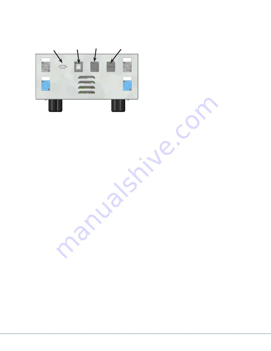
9.3.3
Wall Control Unit Port
Wall
Control Unit
Port
Expansion
Port
SORN
Port
SIDNE
Port
Connection Ports
See the diagram and instructions below to set up
and connect the following ports:
•
Wall Control Unit Port
•
SORN Port
•
SIDNE Port
•
Expansion Port
To enable a connection between the wall-mounted control panel, Visum LED Surgical Lights, and
StrykeCam 2 In-Light Camera, connect the Wall Control Unit Port on the power supply box to the
wall-mounted control panel. Use a Stryker-supplied cable to connect the Wall Control Unit Port to the
Wall Mounted Control Panel.
9.3.4 SORN
SORN is a system that enables device management and networking capability among Stryker equip-
ment. Use an
Ethernet or CAT 5e cable
to connect the SORN port on the power supply box to a local
hospital network port.
9.3.5 SIDNE
SIDNE is a voice activation platform that enables an operation room and its equipment to be con-
trolled with voice commands. Use a USB A (male) to B (male) cable to connect SIDNE to the power
supply box.
9.3.6
Expansion Port (Optional)
SIDNE can control up to four Visum LED Surgical Lights. To do this, a second power control box is
necessary. Use the Expansion port on the first power supply box to connect a second power supply box
to control the additional two lights.
To enable SIDNE to control four surgical lights:
1. Connect the
USB A to B cable from an available SIDNE device port to the SIDNE port on the
first power supply box.
2. Insert a second
USB A to B cable into the Expansion Port on power supply box 1.
3. Connect the cable (leading from the Expansion port) to the SIDNE port on the second power
supply box (see diagram below).
Summary of Contents for MMP200
Page 2: ......
Page 4: ......
Page 106: ...106 S Front View of Connector ...
Page 125: ... 125 S Schematics of Bladder Installation at Bearing 2 Raceway ...
Page 148: ...148 S ...


