Stryker LUCAS 3 Service Manual Download Page 35

LUCAS

®

 3 Chest Compression System – 

Service Manual 

3328798-002, ©2017 Physio-Control, Inc.


Page


35

 of


91


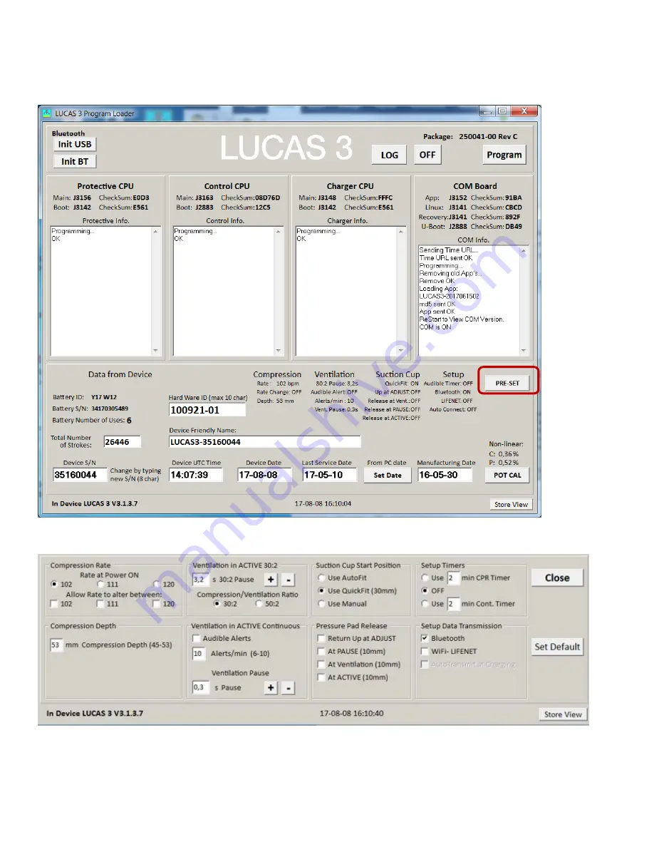
Setup Options - LUCAS 3 Version 3.1 (Part No: 250041-00) 

The Setup Options are configurable for a LUCAS 3 Version 3.1 device. To enter the configuration tool press the 
“PRE-SET” key. 


The preset Options are depicted and described below. To enter the factory default setting, press the key “Set Default”. 
 

Summary of Contents for LUCAS 3

Page 1: ...LUCAS 3 Chest Compression System Service Manual 3328798 002 2017 Physio Control Inc Page 1 of 91 LUCAS 3 CHEST COMPRESSION SYSTEM SERVICE MANUAL ...

Page 2: ...ts 9 Control Panel 10 Electronics Block Diagram 11 Compression Mechanism 12 Device Communication 13 LUCAS 3 Program Loader 13 Software installation 13 Connect the device via Bluetooth 15 Connect the device via USB cable 19 View Error Code 22 Set Device S N Date and Data 25 Change Device S N 26 Set Latest Service Date 26 Store View 26 Checksum 27 Update LUCAS Software 28 Calibrate Linear Sensor 29 ...

Page 3: ...ric Fan and Mesh Grill 57 Compression Module Lubrication 57 Claw Lock Lubrication 58 Replacing Parts or Modules in LUCAS 58 How to Apply Thread Lock Fluid 58 How to Replace the Hood 58 How to Replace the Bellows 60 How to Replace the Compression Module 62 How to Replace the Drive Belt 66 How to Replace the Electric Motor 67 How to Replace the Control PCBA 69 How to Replace the Protective PCBA 70 H...

Page 4: ...LUCAS 3 Chest Compression System Service Manual 3328798 002 2017 Physio Control Inc Page 4 of 91 LUCAS Car Cable 89 LUCAS Power Supply 90 Appendix A wiring diagram 91 ...

Page 5: ...ures in this document are for the example only they are subject to change without matching the latest versions of software Trademarks LUCAS 3 is a trademark of Jolife AB LUCAS 3 Report Generator is a trademark of Physio Control Inc Microsoft and Windows are registered trademarks of Microsoft Corporation in the US and or other countries Specifications are subject to change without notice Definition...

Page 6: ...ve service agreements with Physio Control Service Information Before attempting to clean or repair any assembly in the device the Service personnel should be familiar with the information provided in Preventive Maintenance A qualified Technical Support should inspect any device that has been dropped damaged or abused to verify that the device is operating within performance standards listed in the...

Page 7: ...l performed service where modules are replaced the serial no batch no of each module shall be stated in the service report This information is then sent to Physio Control Inc on a monthly basis The modules that have traceability are Compression Module Electronic PCBs Electric Motor Battery Main Body Support Leg Hood Back plate Recycling Information Important The Battery used in LUCAS shall be retu...

Page 8: ...785 0 26500 00 LUCAS 3 Version 3 1 Chest Compression System Instruction for Use PNs CAT 3326785 1 26500 00 Electrical Hazard Use caution when examining or operating the device without its covers Chemical Hazard The Battery contains chemicals in case of leakage use extreme caution to avoid injuries Never try to open the casing of the Battery ESD Protection Always use ESD protection when handling el...

Page 9: ...LUCAS 3 Chest Compression System Service Manual 3328798 002 2017 Physio Control Inc Page 9 of 91 Device Information LUCAS 3 Components ...

Page 10: ... To unlock the Claw Locks pull the Release Rings Control Panel The User Control Panel is the user interface with which the device can be controlled and monitored through seven button switches and a number of LED s The User Control Panel is situated on the hood and is connected to the protective charger system that sends the signals to the control system For further details on the User Control Pane...

Page 11: ... electronics and the electrical Motor The Motor is connected to the linear unit via a drive belt The electronics is divided in four parts but situated on three separate PCB s 1 The Control System that controls the motor with information from the user interface and from the rotation and linear sensors 2 The Communication System that sends data wirelessly via Bluetooth and WiFi to from computer 3 Th...

Page 12: ...t is fitted to a piston that moves the suction cup piston up and down The Decompression Spring reduces the upstroke force The Suction Cup is adjusted to the patients chest with a servo aid system The suction cup can easily be replaced with respect to hygiene 1 Belt Wheel Large 2 Drive Belt 3 Belt Wheel Small 4 Electric Motor 5 Carry Ball Screw 6 Outer Tube 7 Carry Ball Nut 8 Decompression Spring 9...

Page 13: ...device log and perform sensor calibration LUCAS 3 Program Loader LUCAS 3 program loader is software for updating the program and change the Setup options in LUCAS It can also be used to read errors and warnings from the device and perform the sensor calibration This section explains how the software works LUCAS 3 Program Loader should only be used by trained personnel Antivirus protection and fire...

Page 14: ...Manual 3328798 002 2017 Physio Control Inc Page 14 of 91 Visual differences in screen interface may occur for different software versions 4 Choose installation location on PC and Click Install 5 Click Finish to add the shortcut on the Desktop ...

Page 15: ... can occur Connect the device via Bluetooth When updating the program in LUCAS using the Bluetooth connection there is no need to open the hood 1 Ensure the LUCAS Device is powered OFF and no LEDs are on 2 Press and hold TRANSMIT DATA button for one second to turn on Bluetooth mode ensuring the Bluetooth symbol lights up and flashing Bluetooth symbol TRANSMIT DATA button TRANSMIT DATA button ...

Page 16: ...UCAS 3 device 5 If No Devices Found message displayed click Init BT and try again Note It may take up to 30 seconds for the LUCAS 3 communication app to boot up You may have to click Init BT 2 3 times before LUCAS device shows up on the screen If BT Error occurred repeatedly refer to Bluetooth Connection Error in troubleshooting chapter 6 When Program Loader found LUCAS 3 select the LUCAS that sha...

Page 17: ... of 91 Picture shows connection via Bluetooth for LUCAS 3 Version 3 0 Part No 250039 00 Note differences in J numbers and CheckSum Numbers may occur due to different program versions Check that the serial number S N in the Device S N window is equal as the S N number on the device type label ...

Page 18: ...r LUCAS 3 Version 3 1 Part No 250041 00 Note differences in J numbers and CheckSum Numbers may occur due to different program versions Check that the serial number S N in the Device S N window is equal as the S N number on the device type label 8 To disconnect Bluetooth connection click on OFF button The Bluetooth symbol light will go off ...

Page 19: ...ld be installed 2 Connect an USB cable between the computer and the device the connector is situated at the lower left side of the Control PCB 3 Start the device 4 Start the software by executing LUCAS3_V3_0 exe file Note Different software versions might occur 5 Normally the software detects the device at start If not then Click Init USB 6 When USB connection is established the Program Loader scr...

Page 20: ...vice Manual 3328798 002 2017 Physio Control Inc Page 20 of 91 Picture shows connection via USB cable for LUCAS 3 Version 3 0 Part No 250039 00 Note differences in J numbers and CheckSum Numbers may occur due to different program versions ...

Page 21: ...vice Manual 3328798 002 2017 Physio Control Inc Page 21 of 91 Picture shows connection via USB cable for LUCAS 3 Version 3 1 Part No 250041 00 Note differences in J numbers and CheckSum Numbers may occur due to different program versions ...

Page 22: ... Error and Warnings code in different CPU windows Press SAVE to save the raw log file data to PC only for developers to use Press EXIT to exit LOG view Example 1 Highlight a row according to Date and Time the error occurred from LOG view 2 Click READ and wait to see the Collect errors and warnings from LOG File to show up on the left side of window 3 If the Number of Errors or Warnings are not 0 C...

Page 23: ...Manual 3328798 002 2017 Physio Control Inc Page 23 of 91 Picture shows LOG File content on the left for LUCAS 3 Version 3 1 Part No 250041 00 Note differences in J numbers and CheckSum Numbers may occur due to different program versions 3 2 1 ...

Page 24: ...vice Manual 3328798 002 2017 Physio Control Inc Page 24 of 91 Picture shows Error Codes in CPU window for LUCAS 3 Version 3 0 Part No 250039 00 Note differences in J numbers and CheckSum Numbers may occur due to different program versions ...

Page 25: ...rror Codes in CPU window for LUCAS 3 Version 3 1 Part No 250041 00 Note differences in J numbers and CheckSum Numbers may occur due to different program versions 4 Then refer to Error Codes Tables for more information about how to handle the errors Set Device S N Date and Data LUCAS 3 Version 3 0 Part No 250039 00 ...

Page 26: ...e the Program Loader folder is with the serial number as file name1 At the same time the screenshot will be printed at the selected default printer If no printer is connected a message will appear which can be cancelled the picture will be saved and can be printed at any time 1 An administrative right to the LUCAS3 Tools folder is necessary to save the screenshot This can either be done by right c...

Page 27: ...PU Program ver Main Boot Main Boot Main Boot App Linux Recovery U Boot 3 0 18D1 A20C or E561 9D7F55 12C5 4D61 A20C or E561 46F7 D7EC 2764 DB49 3 1 The Change Order Numbers and CheckSum Numbers are automatically checked by Program Loader 250041 00 Following picture shows the example where to see the CheckSum values on each CPU and COM Board from Program Loader LUCAS 3 Version 3 0 Part No 250039 00 ...

Page 28: ... upper right corner to update LUCAS software The programming process will start and update the software for each CPU Note Do not disconnect the connection during the software update When all four CPUs are updated following window will appear Each CPU window will have OK to indicate the update is complete LUCAS 3 Version 3 0 Part No 250039 00 ...

Page 29: ... Calibrate Linear Sensor After software update is complete Click POT CAL to calibrate Linear Sensor Before you click the Start button please make sure that nothing can influence the movement of the suction cup that the device is in its upright position and that the Suction Cup is approximately 20mm 1 inch down from its upmost position ...

Page 30: ...ion 3 1 Part No 250041 00 1 Click START to calibrate Linear Sensor 2 When the Calibration process starts the progress will be shown in the Control CPU s window When the calibration is done the result is shown in the lower right corner POT CAL In Progress POT CAL Done POT CAL Values 3 Click Store View to print the result POT CAL Acceptable Values C 6 P 3 1 ...

Page 31: ... Control CPU s window the sensor calibration has failed To recalibrate 1 Mute the alarm 2 Check that nothing interferes with the movement of the suction cup 3 The device is upright 4 Click POTCAL to make a new calibration If the second calibration also fails it might be necessary to replace the Compression Module Case 2 If this error Cup not moved to top showed in Control CPU window manually move ...

Page 32: ... 3 sw 3 1 Setup Note First time the USB programming cable is used on the computer PC following has to be done 1 Connect the USB connector to the PC and let the PC install the driver for the USB programming cable 2 Start the Device manager on the PC 3 Expand Ports and select Properties for the used COM Port 4 Select Port Settings ...

Page 33: ...Com Board Plug the USB connector to the computer and assemble the battery to the device Update and Test procedure 1 Start Tera Term software 2 Select Serial and used COM Port OK Note that COM port might be different 3 Select menu Setup Serial port 4 Change Baud rate to 921600 OK 5 Place cursor in the Tera Term window 6 Start Lucas device communication by COM button and press a key on the keyboard ...

Page 34: ... perform Linear sensor calibration 18 When the calibration is completed press the Off button 19 Press the Transmit key on the device and confirm that the blue LED is flashing 20 Start the Service tool software LUCAS3_V3_1_RevX exe with the latest revision and press Init BT button 21 When the device and PC is paired verify the checksums are written in black text and not red that indicates that the ...

Page 35: ...of 91 Setup Options LUCAS 3 Version 3 1 Part No 250041 00 The Setup Options are configurable for a LUCAS 3 Version 3 1 device To enter the configuration tool press the PRE SET key The preset Options are depicted and described below To enter the factory default setting press the key Set Default ...

Page 36: ... operator to change rate during operation The rate is changed by pushing the ACTIVE key 30 2 or continuous during ongoing compressions Compression duty cycle 50 5 Compression mode ACTIVE continuous Factory default setting Continuous compressions with ventilation LED alert 10 times per minute Setup options The device can be setup to provide ventilation alerts of a value between 6 to 10 alerts per m...

Page 37: ...setting Manual The Suction Cup has to be pulled up manually Setup options The device can be setup so that the Suction Cup automatically returns up from the chest when the operator pushes the ADJUST key coming from PAUSE or ACTIVE modes Pressure pad in PAUSE mode Factory default setting The device stops compressions and locks the pressure pad in its Start Position Setup options To allow for chest r...

Page 38: ...ACTIVE 30 2 or continuous modes The CPR Timer stops and resets when the operator pushes PAUSE or ADJUST keys The CPR Timer starts from zero again the next time the operator pushes the ACTIVE 30 2 or continuous key For example if CPR Timer is set for 2 minutes the device will alert after every 2 minutes of compressions Continuous Timer The device measures the time continuously independent of what m...

Page 39: ...AS 3 Chest Compression System Service Manual 3328798 002 2017 Physio Control Inc Page 39 of 91 Troubleshooting In this session it explains the common troubleshooting methods for LUCAS Troubleshooting Table ...

Page 40: ...w is a list on all alarms that can occur on the LUCAS All these alarms are possible to mute for 60 seconds by pressing MUTE button The audible alarms were updated in LUCAS 3 with regards to sound patterns please refer to Instructions for Use PNs CAT 3326785 0 26500 00 and 3326785 1 26500 00 LUCAS 3 Version 3 1 for information ...

Page 41: ...3328798 002 2017 Physio Control Inc Page 41 of 91 Error Codes In the software LUCAS 3 Program Loader it is possible to read error codes from the device Below tables show these codes and the explanation on how to find the cause and corrective actions ...

Page 42: ...ontrol Potentiometer Calibration data CheckSum fault Un calibrated or Too un linear or CPU EE fault Perform a new calibration If un linear fault replace compression module If CPU EE fault replace Control board Delayed 10s High priority Alarm Internal fault contact Technical Support T1_C_INITCURR No 0x20 High Current detected at Start Fault read current to motor or broken driver FET s 12V supply fa...

Page 43: ...tective current read fault I2C communication faults Check for Protective Error s Protective board After 3 start attempt High priority Alarm Self test fault T1_B_OFF No 0x2A No Battery Charger T1 test done time out Charger CPU not done T1 test correct or I2C communication faults Check for Charger Error s Protective board After 3 start attempt High priority Alarm Self test fault T1_C_DOWN No 0x2D Co...

Page 44: ...g Assure un influenced movement of the compression module re test Check Hall Replace motor or compression module High priority Alarm In Pause Disruption of Suction Cup In Active Compressions out of range RUN_TOO_SHALLOW No 0x42 Piston too shallow 50 consecutive strokes 100 bpm 50 strokes Target stroke length 10mm 100bpm Too high load and or too low battery voltage Locked module Assure correct move...

Page 45: ...ntrol CPU Warning Code Explanation Probable Cause Module to check replace User Observation LRG Text T1_START_COM No 0x13 No Communication from Protective and or Battery Charger CPU s at first start I2C communication startup faults Delayed start of Protective or Charger CPU Check cable between boards or Protective board Prolonged startup test time T1_C_INITCURR No 0x20 High Current detected at Star...

Page 46: ...up test time T1_C_DOWN No 0x2D Control not moving down before REW test at first start Motor connections Protective stop by disable line High load at start test Motor Check if start test is done with load Prolonged startup test time T1_P_REW No 0x2E Protective Time out at Reverse test at first start Motor connections Protective POT signal Locked compression module Motor Protective POT Use free pist...

Page 47: ...board Adjust servo switched off RUN_13N No 0x49 13N release force UP too high 13N release 10mm Too high start position or mechanical locked compression movement Assure correct start and movement of the compression module If needed replace the compression module 13N release information signal 3 fast signals Start Position adjustment required COM_P_TIMEOUT No 0x50 I2C Protective Communication Timeou...

Page 48: ...t at start Motor not moved correct or fault current read Protective board check cable between boards or Control board P45 fault After 3 start attempt High priority Alarm Self test fault T1 PISTON RELEASE ERROR Protective release line operation fault at start Current detected at disable test or moved too low at enable test Check cable between boards Protective board or Control board P45 fault After...

Page 49: ...M Internal RAM test detect fault at start Charger CPU faults Protective board High priority Alarm Internal fault contact Technical Support T1 E2 PROM ALARM Internal E2 prom test detect fault at start Charger CPU faults Protective board High priority Alarm Internal fault contact Technical Support T1 POWER OFF ALARM T1 test not ended correct T1 fault detected by other CPU s Check other faults After ...

Page 50: ...ent use manual compressions Not accepted start information signal 3 fast signals Too small patient Too fast mode change Repeated press on button Not accepted start Cup moved held down at PAUSE Cup moved down 10mm by user at PAUSE or Too high start position result in 10mm 13N spring release at next PAUSE after Active Too high Start position resulting too shallow compressions 13N release information...

Page 51: ...ll connectors are connected and that internal cables are intact In some cases a Multimeter instrument can be useful to do measurements with In Appendix A wiring diagram there is a wiring diagram that can be helpful for troubleshooting If the device doesn t start first check the battery and if that s ok check the connections from the Hood and the User Control Panel Spare Parts and Accessories Spare...

Page 52: ...00096 ASSEMBLY FRAME LUCAS 3 STRYKER 160416 01 Main body with support legs mounted 21576 000072 LUCAS 2 POWER INLET 2 2 150417 20 DC inlet connector main body including cable 21576 000085 LUCAS 3 COMMUNICATION BOARD 160420 00 Includes communication board and 3 plastic screws 21576 000097 LUCAS 3 VERSION 3 1 COMMUNICATION BOARD 160420 01 Includes communication board and 3 plastic screws 21576 00008...

Page 53: ...the Terminal 21576 000060 TERMINAL M4 AMP 181949 1067227820 QTY 1 Used to attach Ground Cable from Hood Assembly 21576 000061 SCREW MFX H M3x6 A2 DIN 965 724322040 QTY 4 Used to attach Mesh and Threaded Plate on air intake side 21576 000062 SCREW MFS M3x40 A2 DIN 963 723123842 QTY 4 Used to attach Mesh Fan Washer Fan cable assembly and Threaded Plate 21576 000063 SCREW MRX H M3x50 A2 DIN 7985 7241...

Page 54: ...00055 LUCAS 2 POWER SUPPLY US 150210 00 11576 000056 LUCAS 2 POWER SUPPLY EU 150210 01 11576 000057 LUCAS 2 POWER SUPPLY GB 150210 02 11576 000058 LUCAS 2 POWER SUPPLY JP 150210 03 11576 000059 LUCAS 2 POWER SUPPLY AU 150210 04 11576 000067 LUCAS 2 POWER SUPPLY SWZ 150210 05 11576 000071 LUCAS 2 POWER SUPPLY CANADA 150210 06 11576 000064 LUCAS PCI BACK PLATE 150211 00 Radio translucent 11576 00009...

Page 55: ...ional Tool 300040 00 USB Programming Cable 160423 00 Substances Description Catalog Thread Lock Fluid 11996 000220 PTFE Spray Lubricant 21576 000023 Carry Ball Screw Grease 21576 000018 Compressed Air Can 21300 001335 Software Description Catalog LUCAS 3 Program Loader 3 0 21340 000846 LUCAS 3 Program Loader 3 1 21340 000852 LUCAS 3 Report Generator Free download from LIFENET DT Express Free downl...

Page 56: ...ps Stabilization Strap and the Carrying Bag are checked with the aspect of cleanliness and that the Velcro and buckles isn t worn and fulfils its function Replace if necessary 6 3 in the IFU 6 4 in the IFU 5 Check Replacement Stabilization Strap 6 Check Replacement Carrying Bag 7 Check Update Software Check the software version in the device and update if possible according to LUCAS 3 Program Load...

Page 57: ...sed air Clean dust from areas on the device that require lubrication Remove tape from Carrier Ball Screw hole Compression Module Lubrication Use only specified Carry Ball Screw Grease 21576 000018 With the hood off pull down the Piston and the Adjustment Tube until the Carry Ball Screw is visible in the Lubrication Hole Apply the grease onto the Carry Ball Screw with the syringe 0 5 ml Move the pi...

Page 58: ...he mechanism continuously to work in the lubricant Replacing Parts or Modules in LUCAS How to Apply Thread Lock Fluid The normal amount of Thread Lock Fluid should be corresponding to the diameter of the screw and the Thread Lock Fluid should be applied at the lower end of the screw see picture below This general description shall apply on all use of Thread Lock Fluid on LUCAS according to this ma...

Page 59: ...he four cables between the Hood and the Protective PCB 1 Speaker Cable connected to Control PCB 2 Hood Communication Cable connected to Protective PCB 3 Hood Ground Cable connected to Electric Motor Terminal 4 Hood Power Cable connected to Protective PCB 2 Reassembling Connect the four cables according to Disassembling Make sure that the Hood Ground Cable connector is mounted in front of the ferri...

Page 60: ...e Screwdriver PH1 3 Test Perform a Function Check according to Function Check How to Replace the Bellows 1 Disassembling Take off the suction cup Remove the clamp by removing the two screws with a Torx 10 T10 or Torx 20 T20 Screwdriver Remove the Bellows ring start by treading the bellows over the ring then continue to take off the ring as showed in the picture Correct hood installation ...

Page 61: ...n 2 Reassembling Carefully thread the Bellows over the piston and position it as far up as possible Place the clamp and fixate the bellows by tightening the two screws to 9 0 in lbs 1 0 NM with a Torque Screwdriver Torx 10 T10 or 13 0 in lbs 1 5 NM with a Torx 20 T20 depending on Bellows Clamp The clamp should be positioned as far up as possible ...

Page 62: ...to Replace the Compression Module 1 Disassembling Take off the Suction Cup and remove the Bellows according to Disassembling instruction in How to Replace the Bellows Remove the Hood according to instructions in How to Replace the Hood Disconnect the following cables according to pictures below 1 Protective Linear sensor Cable on the back side of Protective PCB 2 Communication Cable 3 Motor Rotati...

Page 63: ...th a Torx 25 T25 Screwdriver Remove the two screws that hold the Fan Bracket with a Torx 25 T25 Screwdriver and remove the bracket 8 Protective Power Cable 9 Control Power Cable 10 Motor Power Cable use a small flat screwdriver to remove the cables three wires Black top Red middle Yellow bottom Remove if taking out Compression Module Remove if taking out Protective PCB ...

Page 64: ...io Control Inc Page 64 of 91 Loosen the two remaining screws on the other bracket without removing them Remove the four screws that hold the PCB brackets against the Compression Module two screws on each side according to the pictures below with a Torx 10 T10 Screwdriver ...

Page 65: ...ck the Fan Bracket use thread lock fluid and tighten to 35 in lbs 4 0 Nm with a Torque Screwdriver Torx 25 T25 Fasten the Compression Module with four screws use thread lock fluid and tighten to 35 in lbs 4 0 Nm with a Torque Screwdriver Torx 25 T25 Unscrew the two screws on the bracket that are loose apply thread lock fluid and tighten to 35 in lbs 4 0 Nm with a Torque Screwdriver Torx 25 T25 Re ...

Page 66: ...the Antenna Cable Connector and the Communication Cable from the Communication Board as shown in picture below Remove the Belt Cover by removing the four screws with a Torx 10 T10 Screwdriver be careful not to lose the washers Cut the Belt with cutting plier and remove it 2 Reassembling Thread the new Belt over the small Belt Wheel first Continue to Thread it over the Large Belt Wheel and turn the...

Page 67: ...ect the Communication Cable Put back the Hood according to Reassembling instruction in How to Replace the Hood 3 Test Perform a Function Check according to Function Check How to Replace the Electric Motor 1 Disassembling Follow Disassembling instructions in How to Replace the Compression Module to take out the Compression Module Remove the Drive Belt according to Disassembling instruction in How t...

Page 68: ...Apply Thread Lock Fluid to the other two screws and put them on the Motor together with the lock washer and terminal Make sure that the cable outlet is oriented as figure below Slide the Motor onto the Bracket and tighten the screws to 18 8 in lbs 2 0 Nm with a Torque Screwdriver Torx 20 T20 and make sure to angle the terminal so the ferrite of the Hood Power Cable is secured behind the Hood Groun...

Page 69: ...cording to Function Check How to Replace the Control PCBA 1 Disassembling Before disassembling and changing any PCB and if possible connect a laptop and perform Store View using LUCAS 3 Program Loader Follow Disassembling instructions in How to Replace the Compression Module to take out the Compression Module Remove the two remaining screws from beneath and lift out the PCB carefully Warning Alway...

Page 70: ... to LUCAS 3 Program Loader Check that Device S N Time and Date Total Number of Strokes Hardware ID and Device Friendly Name are correct if possible check against Store View performed in Disassembling step If Store View was not possible set Device S N e g 35160021 and Hardware ID e g 100921 00 according to Type Label Total Number of Strokes to 0 zero and Device Friendly Name to LUCAS3 serial number...

Page 71: ...in Disassembling step If Store View was not possible set Device S N e g 35160021 and Hardware ID e g 100921 00 according to Type Label Total Number of Strokes to 0 zero and Device Friendly Name to LUCAS3 serial number according to Type Label 4 Test Perform a Function Check according to Function Check How to Replace the Electric Fan 1 Disassembling Lift of the hood by following Disassembling instru...

Page 72: ...rding to the picture below Put back the Hood according to Reassembling instruction in How to Replace the Hood 3 Test Perform a Function Check according to Function Check When the device is in active mode let it run after approximately 10 minutes the fan should start Now set the device in adjust mode the fan should continue running Check that there is no unusual sound from the fan When the temperat...

Page 73: ... Strap Remove the Bumper Remove Snap Ring by turning the open end of ring to the open edges of the leg shown in the picture and take it out two rings one on each side Remove the Patient Strap Holders two one on each side Lay LUCAS on the side of table with nothing blocking the shaft underneath The round end of spring should be facing up according to the pictures below Turning the Snap Ring to the ...

Page 74: ...e When the Spring is removed from the Angle Shaft turn the device over so the press fitted side is facing up Using the metal Pin or similar tool and Hammer push the bottom non press fitted Angel Shaft out of Support Leg Always knock out the non press fitted Angle Shaft first Knock the Spring from round end out of shafts Spring with a round end facing up non press fitted side Spring with a flat end...

Page 75: ... Page 75 of 91 Turn the leg on the other side and use the Angel Shaft Tool optional tool or similar tool with a Hammer to knock out the press fitted Angle Shaft which is fitted into the Main Body The bottom non press fitted Angel Shaft Angel Shaft Metal Pin Press Fitted Side with Key ...

Page 76: ...t from LUCAS Insert the Angle Shafts start with the one that is press fitted into the Main Body oriented as picture below Knock it down so that it is completely flush into the Support Leg On the same level Angle Shaft Tool Use this end to remove Use this end to install During this reassembling step the keyways for the Spring should always be pointing towards the Compression Module on both shafts N...

Page 77: ...haft by hand force until it stops Ensure that the keyways for the spring are aligned with each other Insert the Spring with the rounded end first all the way down through both Angle Shafts Use a Mandrel to fully seat the spring into the Angle Shaft Turn the leg inwards to its correct position Ensure the L shaped end of the spring is properly seated inside the Angle Shaft ...

Page 78: ...ped side of the spring to make sure it is still seated in the Angle Shaft A mandrel can be used to tap it into place if not fully seated Put the Patient Strap Holder in place two sides Install Snap Ring according to the picture below two sides place the open end of the ring downwards Slide the Bumper up over the support leg note the direction of the bumper skirt edge should be on the bottom Thread...

Page 79: ...eg If that doesn t work contact Physio Control to get a new label with the same SN and Notified Body number The Notified Body number 0434 as shown in picture above may be 2460 3 Test Do the following tests to verify that the repair replacement has been performed correctly Check the locking function by locking and unlocking against the Back Plate Slide the Bumper up over the patient strap holders S...

Page 80: ... Hood according to instructions in How to Replace the Hood Cut out two cable ties Disconnect the antenna cable connector from Communication Board Remove the antenna board from the belt cover 2 Reassembling Pre bend two cable ties at the bend line marked in red as shown in the picture Bend the tip of the cable tie to make it easier go through the hole Use a third cable tie marked with blue arrow in...

Page 81: ...ove the tapes protective top layer Place the antenna on top of the transfer tapes and against the surfaces marked with red arrows and in between flanges marked with green arrows Close and tighten the cable ties by hand until the antenna is secured as shown in the pictures below with the cable tie closing position against the edge of the antenna board Transfer Tapes ...

Page 82: ...o Replace the Hood 3 Test Perform a Function Check according to Function Check How to Replace the Communication PCB 1 Disassembling Before disassembling and changing any PCB and if possible connect a laptop and perform Store View using LUCAS 3 Program Loader Follow Disassembling instructions in How to Replace the Controller PCB to take out the Controller PCB Use a plier carefully cut off 3 plastic...

Page 83: ...lat nose plier right up against the nut shown in the picture below Put back the Controller PCB according to Reassembling instruction in How to Replace the Controller PCB 3 Programming Connect a laptop and program the Protective PCB according to LUCAS 3 Program Loader Check that Device S N Time and Date Total Number of Strokes Hardware ID and Device Friendly Name are correct if possible check again...

Page 84: ... Compression Module Follow the instructions in Section Replace the Controller PCB Follow the instructions in Section Replace the Protective PCB Warning Always use ESD protection when handling PCB s Remove the four Torx 20 screws to remove the Main Body Lid Use the extraction tool to remove the wires from the Power Inlet With the wires removed you can now remove the nut and Power Inlet ...

Page 85: ...hite arrow on top Install the Power Inlet nut and tighten to 9 in lbs 1 0 Nm Insert the Power Inlet wires with the red on top Install the Main Body Lid and tighten all four Torx 20 screws to 13 in lbs 1 5 Nm Re install the Compression Module Controller PCB Protective PCB and Hood 3 Test Perform a Function Check according to Section Function Check ...

Page 86: ...he instructions in Section Replacing the Power Inlet If replacing the Main Body follow the instructions in Section Replace the Support Legs Warning Always use ESD protection when handling PCB s 5 Reassembling Re install the Power Inlet using instructions in section Replacing the Power Inlet Install the Main Body Lid and tighten all four Torx 20 screws to 13 in lbs 1 5 Nm Re install the Compression...

Page 87: ...use the Electrical Motor is affected instead push slowly in one long stroke Push the Suction Cup back up to its top position check that it runs smoothly and without unusual noise 8 Claw Lock Mechanism Check Check for play between the Release Ring and the Support Legs Pull the Release Ring gently to unlock the mechanism and open the Claws Move your finger around in the Release Ring verify that you ...

Page 88: ...light The LED will then blink each ten strokes ventilation alert 5 Change mode to ADJUST pull the Suction Cup down to test the Adjustment Servo Push the Suction Cup back up to its top position Check that it runs smoothly 6 Connect a charger to the device and check that the charging sequence begins the battery LED s show a running light Disconnect the charger 7 Turn the device off 8 Testing Transmi...

Page 89: ...ttery Charger The battery charger is sold as an accessory For more information about different country specific variants see the list of Accessories There are no serviceable parts in the battery charger if broken replace with a new LUCAS Car Cable The car cable is sold as an accessory with the product cat 11576 000048 ...

Page 90: ...7 Physio Control Inc Page 90 of 91 LUCAS Power Supply The power supply is sold as an accessory For more information about different country specific variants see the list of Accessories There are no serviceable parts in the power supply if broken replace with a new ...

Page 91: ...LUCAS 3 Chest Compression System Service Manual 3328798 002 2017 Physio Control Inc Page 91 of 91 Appendix A wiring diagram ...

Reviews: