


d
e
f
g
h
©
Street
Crane
Co
Ltd
Page
42
of
103
Ref:
D3256
rev.
B
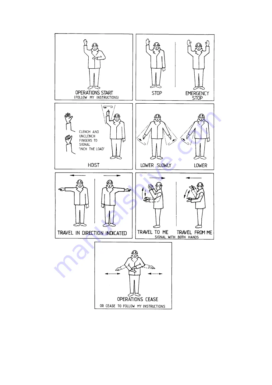
Figure
29
‐
Recommended
Hand
Signals
4.3
REMOTE
CONTROLLED
CRANES
/
HOISTS
To
prevent
unauthorised
use,
the
operator
should
either
retain
the
transmitter
in
their
possession
or
remove
the
key
from
its
key
lock
switch
and,
for
short
periods,
retain
the
key
in
their
possession.
For
longer
periods,
or
when
the
crane
is
not
in
use,
the
transmitter
should
be
deposited
in
a
designated
safe
storage
place.
When
the
transmitter
is
fitted
with
a
belt
or
harness,
the
operator
should
be
wearing
the
harness
before
switching
the
transmitter
on.
This
will
prevent
accidental
operation
of
the
crane
/
hoist
whilst
fitting.
The
transmitter
should
also
be
switched
off
before
removing
the
harness.
Summary of Contents for ZX6
Page 2: ......
Page 4: ...defgh Street Crane Co Ltd IV THIS PAGE IS INTENTIONALLY BLANK ...
Page 99: ...defgh Street Crane Co Ltd Ref D3256 rev B Page 99 of 103 NOTES ...
Page 100: ...defgh Street Crane Co Ltd Page 100 of 103 Ref D3256 rev B NOTES ...
Page 101: ......
Page 102: ......


