Page 1
W
HEN
USING
ELECTRICAL
EQUIPMENT
,
ALWAYS
FOLLOW
THESE
BASIC
PRECAUTIONS
:
IMPORTANT SAFETY INSTRUCTIONS
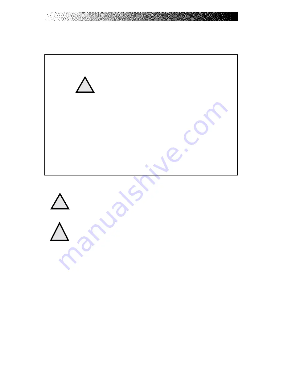
This symbol appearing throughout this manual
means Attention! Be Alert! Your safety is involved.
The following definitions apply to the words “Danger” and “Warning”
found throughout this manual:
DANGER
- Used to call attention to IMMEDIATE hazards which, if not
avoided, will result in immediate, serious personal injury or loss of life.
WARNING
- Used to call attention to POTENTIAL hazards that could
result in personal injury or loss of life.
READ ALL INSTRUCTIONS BEFORE USING THE MACHINE.
To reduce the risk of electrical shock, always unplug
the external power supply from the AC wall outlet
before cleaning, maintaining, or repairing.
To reduce the risk of burns, electric shock, or injury
to persons:
1.
The external power supply should always be unplugged from the AC wall
outlet before removing or installing parts. Never make adjustments or
repairs while an exercise program is in progress.
2.
Close supervision is necessary whenever the machine is used by or near
children, invalids, or disabled persons.
3.
Keep your hands away from all moving parts and keep your feet on the
pedals while exercising. Do not operate the machine with the side covers
removed.
DANGER
!
WARNING
!
!
SAFETY GUIDELINES
Summary of Contents for STRATUS 3300 CE
Page 1: ...Stratus Systems Owner s Manual...
Page 66: ...Page 59 FIGURES Figure 11 Cover Fasteners...
Page 67: ...Page 60 FIGURES Figure 12 Cover Fastener Locations 3300 CE...
Page 68: ...Page 61 FIGURES Figure 13 Cover Fastener Location 3900 RC...
Page 69: ...Page 62 Figure 14 Right Side View 3300 CE FIGURES...
Page 70: ...Page 63 Figure 15 Left Side View 3300 CE FIGURES...
Page 71: ...Page 64 FIGURES Figure 16 Right Side View 3900 RC...
Page 72: ...Page 65 FIGURES Figure 17 Left Side View 3900 RC...
Page 73: ...Page 66 FIGURES Figure 18 Seat Adjustment Pin Assembly 3300 CE...
Page 74: ...Page 67 FIGURES Figure 19 Seat Assembly 3900 RC...
Page 75: ...Page 68 FIGURES Figure 20 Drive Chain Tension...
Page 76: ...Page 69 FIGURES Figure 21 Intermediate Shaft Assembly...
Page 77: ...Page 70 FIGURES Figure 22 J Bolt Assembly...
Page 78: ...Page 71 FIGURES Figure 23 Crank Assembly...
Page 79: ...Page 72 FIGURES Figure 24 Alternator Flywheel Assembly...


