Page 40
The following tests must be performed while the console is in the DIAGNOSTIC
mode. To activate the DIAGNOSTIC mode, press the [+ ARROW], [1], [0], [7],
[ENTER]. If the console fails any test, the console should be replaced or ex-
changed.
Display Test
Use this test if the console display or the text bar exhibits blank spots during use.
This test checks for inoperable light emitting diodes (LEDs) in the console display
and the text bar. If any LED will not light, replace the console.
1.
Press [0] to start the test.
2.
All LEDs in the console display and text bar should flash.
3.
Press [CLEAR] to end the test.
Speaker Test
Use this test to make sure the console speaker is fully operational. The speaker
will ascend and then descend through the musical scale.
1.
Press [1] to start the test.
2.
Press [ENTER] to pause the test. Press [CLEAR] to end the test.
Keypad Test
Perform this test if you are having trouble entering data into the console. If you
cannot enter the DIAGNOSTIC mode code due to an inoperable keypad, replace
the console.
1.
Press [2] to start the test.
2.
The display LEDs will light up in an L-shaped formation, representing
the keypad matrix. Pressing a button on either the exercise program
keypad or the function keypad will light an LED within the outline on
the display that corresponds to that button’s position on the console.
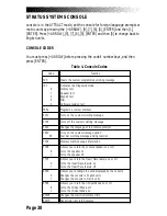
CONSOLE DIAGNOSTIC TESTS
Summary of Contents for STRATUS 3300 CE
Page 1: ...Stratus Systems Owner s Manual...
Page 66: ...Page 59 FIGURES Figure 11 Cover Fasteners...
Page 67: ...Page 60 FIGURES Figure 12 Cover Fastener Locations 3300 CE...
Page 68: ...Page 61 FIGURES Figure 13 Cover Fastener Location 3900 RC...
Page 69: ...Page 62 Figure 14 Right Side View 3300 CE FIGURES...
Page 70: ...Page 63 Figure 15 Left Side View 3300 CE FIGURES...
Page 71: ...Page 64 FIGURES Figure 16 Right Side View 3900 RC...
Page 72: ...Page 65 FIGURES Figure 17 Left Side View 3900 RC...
Page 73: ...Page 66 FIGURES Figure 18 Seat Adjustment Pin Assembly 3300 CE...
Page 74: ...Page 67 FIGURES Figure 19 Seat Assembly 3900 RC...
Page 75: ...Page 68 FIGURES Figure 20 Drive Chain Tension...
Page 76: ...Page 69 FIGURES Figure 21 Intermediate Shaft Assembly...
Page 77: ...Page 70 FIGURES Figure 22 J Bolt Assembly...
Page 78: ...Page 71 FIGURES Figure 23 Crank Assembly...
Page 79: ...Page 72 FIGURES Figure 24 Alternator Flywheel Assembly...

